So tonight I had a bit of an epiphany while have the Trident hooked up to the tape machine. We were running into feedback while input monitoring on the tape machine while in line input on the trident. Well, I've been viewing this console as more of an inline console rather than a split.
Justin
The way those great analog consoles were meant to work is you directly hear your inputs channels while recording. Then once recorded, you hear the playback of the recorded channels through the monitor row while using the inputs to record more stuff. Example: After recording the drums & bass we could hear the playback of the kick from channel #1 of the tape machine on the monitor-row while using input channel #1 on the desk for recording an overdub.
Bob
I see that now. I guess it just wasn't viewing this the way I was hoping it would.
This may take a bit for me and Brian to chat about this. Because the trident has 16 channels, but only 8 group outputs that are really only 4 (group 1/5, 2/6, etc). It's severely limiting if you ask me. But maybe that's just me being used to unlimited channels via protools.
I understand. Back in the day, we made big-use out of the direct outputs. Not all signals need go through the busses. Many times I would take a signal, let’s say the kick again, into the console and direct out of that channel patching to an outboard EQ then patch out of the EQ into a limiter and directly out of the limiter and patch into a channel of the tape machine… You can also use your FX sends as outputs to the recorder.
There really are more in's & outs than 8 X 4. You can always use two of the monitor-row channels for many channels of Pro Tools playback into the studio Monitors and headphones. That console gives you warm fat EQ for recording and warm fat EQ for mixing stems too. I wouldn’t get your mind into a "severely limiting” mode. Only think a little differently and let that console help the sounds of your music.
That old English board has more soul that all the unlimited channels at 96K that Pro Tools rig dream of…
Bob
Mr. Patchbay Q & A Blog

-
 Trident FeedbackTrident Console FeedbackJustinOn March 3, 2018, at 5:29 AM
-
 Stereo HeadphonesStereo headphones with 3 wiresJesse AllainOn Oct 29, 2017, at 2:04 PM
On Oct 29, 2017, at 2:04 PM, Jesse Allain
Hello Mister Patchbay,
I have a pair of stereo headphones with 3 wires inside the cable. They are red, gold and green and appear to be some type of colored copper wire that is both insulating and conductive at the same time.
I have soldered a new TRS connector on the end and attached red to tip, gold to ring and green to sleeve but I only get audio from one ear instead of two When I insert the plug in to the tip only I get both channels.
Do you know what I should do to rewire this? Thanks in advance for your help.
--
Jesse Allain
Access Coordinator
Certified Audio Engineer, SBE
Member, Audio Engineering Society
Hey Jesse,
Sounds like a good choice on your wiring. Since it is not working correctly, I would try swapping the gold to the sleeve and the green to the ring. It has to be one of the nine ways three wires could be connected.
Bob
On Oct 31, 2017, at 8:49 PM, Jesse Allain
Hi mister patchbay,
This is Jesse, you gave me advice on wiring a new connector on stereo headphones the other day. Your suggestion worked out very well and I think that the color scheme is gold wire = shield, red wire = right channel and blue wire = left.
At first I was getting confused with the blue wire because it looked bluish green to me (maybe I’m colorblind) so I though of the old “green is ground” adage from AC wiring.
Anyway, thanks again for all of your help, you’re a really great resource and have helped me out a lot.
Thanks,
Jesse
--
Jesse Allain
Access Coordinator
Certified Audio Engineer, SBE
Member, Audio Engineering Society
You are welcome sir. Anytime you need help, just ask.
Bob
-
 How long in total?How long in total is a 1 foot, 2 foot, 3 foot patch cable?MikeyOn Sep 16, 2017, at 8:55 AM
On Sep 16, 2017, at 8:55 AM, Mikey ***** <***********@gmail.com> wrote:
Quick Q:
Are your Mr. PB TT patch cables measured tip to tip. i.e., how long in total is a 1 foot, 2 foot, 3 foot patch cable?
Thanks
Mikey
On Sep 16, 2017, at 3:31 PM, Bob Hickey
Hey Mikey,
The one-foot TT cable is 13.5” tip-to-tip
The two-foot TT cable is 25.25” tip-to-tip
The three-foot TT cable is 29.25” tip-to-tip
Sincerely,
Bobby Hickey
817-926-9535 -
 Burnisher for a TT?Do you have a burnisher for a TT patchbay for sale? How often should you use one?Robert FrostOn Sep 17, 2017, at 10:44 PM
On Sep 17, 2017, at 10:44 PM, Scot <**************@me.com> wrote:
Do you have a burnisher for a TT patchbay for sale? How often should you use one?
Thanks
Scot
Hey Scott,
I do not own one sir. You should never use one. Burnishing tools cause extreme jack spring wear which may cause intermittent signals.
Below is how to clean your patchbay jacks:
Take a clean patch cable, insert and withdraw into your patchbay jack four or five times. This causes a mechanical wiping action that cleans both springs that make contact with the plug and switching contacts. Then clean your patch cable plug with a moist cloth and repeat on the next channel.
Bob -
 Rewire StudioI am planning to rewire my studioJulesOn Sep 21, 2017, at 7:48 AM
On Sep 21, 2017, at 7:48 AM, Jules <*********@ymail.com> wrote:
Mr. Patchbay,
I am planning to rewire my studio. I have a Soundcraft MH3 as main console, and I would like to connect every outputs and inputs to a patchbay system composed of 3x ADC & 1 x Bittree patchbays.
My questions are:
1. How do I set up Half Normal and Full normal of 3x ADC & 1 x Bittree patchbays?
2. How do I set up a patchbay for Live room mic with 48 Phantom power?
3. How to I connect the cable on the patchbay for Reverbs units?
I have attached the layout that I have in mind.
Please feel free to make any changes or add your inputs or corrections.
God Bless you for the Help that you provide to us!
Jules
Hey Jules,
Your ADC patchbays are already full-normal. To change that you need to take the unit(s) apart and move the normal jumpers on the top-row from the normal pins to the standard hot and ring. You will need to cut and solder or get a wire-wrap tool: https://www.specialized.net/jonard-ok-industries-wsu-2224-wrap-strip-unwrap-22-24awg-std.html
For your phantom power mic you need to set the grounds either bussed( all connected together) or GVS (grounds vertically strapped).
All effects and reverbs use NO NORMALS because the output would feedback into the input.
You verbs would be standard tip, ring, sleeve balanced.
Bob
-
 Type of Punch Tool?What type of punch tool do I need?JeffreyOn Sep 20, 2017, at 9:31 PM
On Sep 20, 2017, at 9:31 PM, Jeffrey ***** <*******@gmail.com> wrote:
Hello! I am writing you because I have a couple of questions regarding an ADC 48 point patchbay with a punch block.
I am working on this project on my own and do not have much experience with this type of equipment. I have been doing my research and for the life of me can not get a clear answer on the type of punch tool that would need fort this patchbay.
Do you sell punchtools for an ADC patchbay with the punchblock that has the normaling and TRS connections?
If you do not sell them and it is not too much trouble, could you inform me on what I should be looking for?
Much appreciated
Jeff
hey Jeff,
No problem dude. I do not sell the punch tools. I only give them away when someone buys a punch type patchbay.
What you need is the ADC Q115: https://www.markertek.com/product/adc-q115/adc-commscope-q115-qcp-manual-punch-tool
There is also the QB-2 for more money but the Q115 works just fine: https://www.markertek.com/product/qb2/adc-commscope-qb-2-qcp-impact-punchdown-tool-for-qpc-ii-propatch-panels
Here is how to use your ADC punch tool: https://misterpatchbay.com/patchbays/movies-how-to-wire-your-patchbay.html
Sincerely,
Bobby Hickey
817-926-9535 -
 Burnisher tool?Should I use a burnisher tool?ScotOn Sep 17, 2017, at 10:44 PM
On Sep 17, 2017, at 10:44 PM, Scot ************s <****************@me.com> wrote:
Do you have a burnisher for a tt patchy for sale? how often should you use one?
Thanks
Scot
Hey Scot,
I do not own one sir. You should never use one…
Cleaning of jacks can be accomplished only by inserting and withdrawing a clean plug into the jack five or six times. This causes a mechanical wiping action that cleans both the springs that contact the plug and the switching contacts.
Sincerely,
Bobby Hickey
817-926-9535 -
 Back Mirror Front?Does the back panel mirror the front exactly?Frank LoCrastoOn Aug 29, 2017, at 12:23 PM
On Aug 29, 2017, at 12:23 PM, Frank LoCrasto
Hi Mister Patchbay,
I've got an ADC QCP 96 pt tt punch patchbay. On the back panel of the patch bay, the top row from left to right is numbered 1, 49, 2, 50, 3, 51 and so forth. The bottom row from left to right is numbered 25, 73, 26, 74, 27, 75 and so forth. My question is does the back panel mirror the front exactly? Does "1" correspond to the upper left input on the front of the patchbay and "25" on the lower left input? Or is "49" the lower left input on the front of the patchbay?
thanks!
fRaNk
--
http://www.franklocrasto.com/
franklocrasto.bandcamp.com
Hey Frank,
Channel one is upper left. Channel 49 is under that channel being the first channel bottom left. The reason they are setup that way is if you want to set the normals, you only need to punch a wire from #1 to #49 right next to it etc.
96 Point Patchbays:
To make Full Normal wire from Blue #1 to Blue #49 ; wire from Blue #2 to Blue #50
From Orange #1 to Orange #49; From Orange #2 to Orange #50 etc.
To make Half Normal wire from Red #1 to Blue #49
From Black #1 to Orange #49; wire from Red #2 to Blue #50 From Black #2 to Orange #50 etc.
https://www.misterpatchbay.com/patchbays/movies-how-to-wire-your-patchbay.html
Sincerely,
Bobby Hickey
817-926-9535
-
 Macbook to PatchbayI can't figure out how to get my Macbook to myPatchbayJesse AllainOn Aug 12, 2017, at 2:06 PM
On Aug 12, 2017, at 2:06 PM, Jesse Allain
Hello,
I have my patchbay mostly wired and for some reason I can't figure out how to get the 1/8" TRS of my macbook out to 2 channels of my adc patchbay. My patchbay has only TrS connections for each channel. I tried twisting the red wires from both cables and soldering to the Tip l, twisting the blacks for ring and twisting the shields for sleeve And it sounds phasey and weird.
Thanks in advance...
Jesse allain
--
Jesse Allain
Access Coordinator
Certified Audio Engineer, SBE
Member, Audio Engineering Society
Ashburnham Westminster
Community Access Television
www.awcatv.org
Hey Jesse,
The tip (hot) of your 1/8” TRS from your Mac goes to the tip of the left channel on your patchbay. The ring ( low line) of your 1/8” TRS from your Mac goes to the tip of the right channel on your patchbay. The ground can go to either channel or both. Now you will have a correct stereo signal.
Sincerely,
Bobby Hickey
817-926-9535
On Aug 12, 2017, at 9:58 PM, Jesse Allain
Awesome, thank you so much. You are a great source of knowledge and I really appreciate your help with setting up my studio. I got the equipment you suggested and it works great.
Very Cool. Glad to help. -
 Normal for Effects?Can I normal my Effects?Chris MehalsoOn Aug 6, 2017, at 11:11 PM
On Aug 6, 2017, at 11:11 PM, Chris Mehalso
Got another one for you . . .
On my last normalled patch bay config, I had my compressors set up with the outputs directly over the inputs. I don’t remember there ever being a feedback problem . . . but how would I know? When I plugged a cable in so I could have actually heard something, I would have broken the loop. I was about to do the same thing with a Korg Kaoss Pad processor in my new config, and realized that might be a dumb way to do it with the feedback loop risk.
So . . . in a normalled configuration, is it unwise to go top to bottom with processing gear? Does feedback happen without signal present? I would think even cycle hum in the system would eventually cause it to feedback even if I couldn’t hear it as it was happening . . . yet I never observed that happening in my rig.
Please let me know. THANKS!
Chris Mehalso, CTS COHERENT MEDIA SYSTEMS SPECIALIST BTX TECHNOLOGIES, INC. // www.btx.com // chrism@btx.com // Direct Line: 904.885.0054
Hey Chris,
The rule for outboard gear and effects is never use normals because the output is returning to the input and will, in fact, cause a feedback loop. So just de-normal the top-row from the bottom-row and you will be fine. No advantage for normals on your effects anyway.
Bob -
 Headphone AmpHelp Needed wiring Headphone AmpChris MehalsoOn Aug 4, 2017, at 6:57 PM
On Aug 4, 2017, at 6:57 PM, Chris Mehalso
Hi Mister Patch Bay –
I am having trouble. Possibly more than one problem. I have 8 outputs on my sound card, so I created 8 outputs on my TT patch bay. One of those stereo pairs is normalled to a pair directly below it that goes to a little headphone amp. The headphone amp accepts TRS input, so I had to build a cable that takes the two balanced channels and combines them onto one TRS that I could plug into the headphone amp.
Problem #1 is that I simply cannot get the normals to make sound. I assume this is a problem with the patch modules or my cables from the sound card. I will address this myself. But I tested it by simply using patch cables to grab sound from a known working output. More problems then . . .
I am getting a loud hum. I also noticed that the click track sounds clear and appears on BOTH EARS when I only have one of the two patch cables connected. Then I connect the second cable the sound volume drops significantly and the quality is really poor. This seems like a phase error because I built the cable wrong. Here’s how I built it:
The TRS end:
T – both red conductors from two cables
R - both black conductors from two cables
S - both ground conductors from two cables
The patch bay end:
Left cable
Black conductor – T
Red conductor – not connected
Ground conductor – S
Right cable
Red Conductor – T
Black conductor – not connected
Ground conductor – S
I thought by doing this I would be creating a stereo unbalanced feed from two mono balanced feeds . . . but I appear to be doing something wrong. Can you help??
THANKS
Chris Mehalso, CTS COHERENT MEDIA SYSTEMS SPECIALIST BTX TECHNOLOGIES, INC. // www.btx.com // chrism@btx.com // Direct Line: 904.885.0054
Hey Chris,
The input to your TRS headphone amp should be as follows: Left channel hot goes to the tip of your 1/4” TRS cable that plugs into your headphone amp. The Right channel hot goes to the ring of your 1/4” TRS cable that plugs into your headphone amp. The ground on the 1/4” TRS cable that plugs into your headphone amp can come from either left or right channel ground.
That’s it. It is two mono channels that drive the stereo headphones.
Sincerely,
Bobby Hickey
817-926-9535
-
 Unbalanced TRS InsertConsole with unbalanced TRS insert send and return jacksChristopherOn Apr 25, 2017, at 6:34 PM
On Apr 25, 2017, at 6:34 PM, Christopher <****@me.com> wrote:
Hey Mr. Patchbay! I have a console with unbalanced TRS insert send and return jacks. I’ve connected the send to the top row of a half normal’d Bittree patchbay. The return is connected to the bottom jack of the patchbay. In this configuration, I don’t get an audio signal from my console. If I unplug the insert send and return cables from the console I get audio signal. I’m missing something on how to wire these to my patchbay. Do you have a tutorial available or are you able to advise?
Thanks!
Chris
Hey Chris,
When you insert a 1/4” TRS cable into your console (with the tip as the send and the ring as the return) the other end should go to your patchbay like this: The tip ( hot / send ) goes to the tip (hot) on the top-row of the patchbay. The ring goes to the tip ( hot / return ) on the bottom-row. Then the ground can go to either ground on the patchbay. Some people buss the ground to the other row’s ground. Some people buss that ground not only to the other row but also to the rings on both rows. Me I just go to one ground and leave it be. The patchbay must be full or half normal to complete the send / return loop.
Sincerely,
Bobby Hickey
817-926-9535 -
 What Cable on ADC?What is the solid core cable ADC used in Patchbays?EricOn Feb 24, 2017, at 3:27 PM
On Feb 24, 2017, at 10:07 AM, ****** <***@me.com> wrote:
Bob
Hope all is well with you and yours. Somebody asked a me a question I should know the answer to , but after 2 days of digging and still not finding the answer I admit defeat and come to the best source of Patchbay information
What is the Belsen solid core cable ADC used in Bays like the PPA series?
Thanks as always
Eric
srgv@me.com
Sent from my iPhone
On Feb 24, 2017, at 3:27 PM, Bob Hickey
Hey Eric,
They do not number most of the Belden cabling for the ADC stuff. I would LOVE TO KNOW THAT ANSWER!
Bob
On Feb 27, 2017, at 9:55 AM, ******<****@me.com> wrote:
Bob
It's Belden 8450
Walked into Electronic Supply to pick up some Dsubs and the Counter guy introduces me to the Belden rep who was the ADC rep for 15 years l After swapping stories he answered the question and gave me a 25 ft sample !
I sent a guy named Chase your way today, trying to talk him out of $100 Chinese bays.
If you have sometime poke your head in at Realgearonline.com, we try to keep it respectful while still keeping the vibe of a bunch of AE's talking over beers!
It's not yet the cluster known as Gearslutz, and many could use your knowledge!
Eric
If I ever get done wording I have a tone of extra jacks I'll donate to your continued endeavors!
Sent from my iPhone
Thank you so much. I never knew the wire number! Yes it works great. Easy to work with and stays where you bend it.
Bob
-
 Dangerous Monitor STCue Amp Output of a Dangerous Monitor STJah Guide MusicOn Feb 21, 2017, at 1:24 PM
On Feb 21, 2017, at 1:24 PM, Jah Guide Music
Greetings Sir, I trust all is well with you. I truly appreciate your wisdom on all of my queries. I am hopeful you do not feel as though I'm taking advantage of your kind nature. But I've found it challenging to get answers to my questions elsewhere.
Anyways I have another question based on the same punch block patchbays we've discussed before. I am looking to Normal the Cue Amp Output of a Dangerous Monitor ST (coming out of the unit as a single XLRm). It's wired as:
Pin 1: Ground
Pin 2: Right channel
Pin 3: Left channel
The other unit is a headphone amp who's inputs are standard 1/4" TRS.
Dangerous recommends this:
Which is a XLR to dual TS cable.
My question is not so much what cables, but how do I wire the punch points for the Cue Amp. What wires go where? Because I have to take the 1 output and connect it to 2 punch block points to have the stereo signal go from the Monitor ST into the headphones amp.
Sorry if I am not clear, not sure how else to ask. Sorry for being long winded!
Thanks again for all your help.
Right channel goes to Hot (RED on a punch down bay) on any patchbay channel. Left channel goes to Hot (RED on a punch down bay) on a different patchbay channel. Ground goes to ground on either the right or left channel. Then you can use a scrap-wire to go from the ground to the other channel’s ground. Easy.
On Feb 22, 2017, at 5:16 AM, Jah Guide Music
Hey Bob. I was wondering if you also make and sell cables? If so what brand wires and connectors do you use?
And how much would you charge me for this cable I just wrote you about? I would need 10' length, XLRf (pin 1=gnd, pin 2=right channel, and pin 3=left channel) to 2 TS. 6" fan out, with the TS sides being Blunt for the punch down PatchBay.
Thanks.
Sent from my iPhone
You do not need me to make you a cable… Take a mic cable and cut the male XLR off. Now strip the insolation three or four inches back. Take the hot lead Pin-2 ( you may have to open the XLR-Female end and see which color the hot lead is) and punch it just like I told you last night. Punch this lead to the RED (HOT) on a channel. This is your RIGHT channel.
Now take the pin-3 lead and punch to the RED on the channel next to the one you just punched. This is your LEFT channel. Punch the ground to either of the these channels. You will be all set.
Bob
-
 Determine Normal StatusAttempting to determine the normalling statusJah Guide MusicOn Jan 24, 2017, at 9:49 PM
On Jan 24, 2017, at 9:49 PM, Jah Guide Music
wrote:
Greetings Sir. I trust all is well with you. This is a bit of a stretch, but since I know you are a patch bay guru I thought I’d at least ask. I’ve attached some pics of a patch bay I recently bought in which I am attempting to determine the normalling status. Not sure you can properly see, but just thought I’d ask.
Thanks for any info you can provide.
Jah Guide Music
Hey Jah Guide,
That is an ADC patchbay that, from what I can see, looks to be full normal. If the white normaling jumper-wire that goes from the normal post on the bottom-row , goes to it’s “own” post then for sure it is FULL NORMAL. If that white wire goes to a post on the top-row that also has a red wire wrapped around it, then it would be half normal. Pretty sure that is full normal.
Sincerely,
Bobby Hickey
817-926-9535 -
 Novice to StudioI'm a novice to studio patch bay setupBruceOn Sep 5, 2016, at 7:52 PM
On Sep 5, 2016, at 7:52 PM, Bruce ****<*******@roadrunner.com> wrote:
Hello,
I am a novice to studio patch bay setup and I am wondering if you could give me advise on what type of patch bay I should/could purchase from you that would work with the following setup.
Board will be a Presonus StudioLive 32.4.2ai
iMac computer will be connected to board using FireWire
Recording software will be Logic ProX
I will be running monitors thru a presonus central station rack unit
I will have a separate control room and a separate live room.
In live room I will have a snake with 16 xlr and 4 1/4" returns that will run into control room.
In the control room I want to have a rack that will have several compressors, an eq, and a few preamps. I am not sure of exact models but there will be some outboard gear.
Any help you can provide on what patch bay I should use or if I need a custom one made, I would be very grateful as this is my first go at setting up a home studio.
Any questions you need to know, just ask.
Thanks,
Bruce ******
Sent from my iPad
On Sep 5, 2016, at 9:01 PM, Bob Hickey
Hey Bruce,
I would suggest the Audio Accessories Quick Switch Mini. This is one of the best patchbays on the market. Retail is $999.99 without cables. I offer this with custom cables for much less money:
With this patchbay you can change the normals ( http://www.misterpatchbay.com/normaling/normal.html ) and the grounding quickly. Also the E3 connectors on the rear of the chassis let you move / remove / change and cable(s) for future changes to your studio or changes to the way the channels are grouped in the bay.
Plus if you do not know which outboard rack-gear you will be buying it lets you get the patchbay from me wired to your current setup and add the other outboard gear’s cables when you know which connectors you will be needing. Then I would build XLR, TRS or DB-25 cables as needed and you can plug those cables right into the back of the patchbay.
If you know what connectors you will need on all 96 channels but do not yet know what normals you need this is a good option but connectors are soldered before shipping: http://www.misterpatchbay.com/patchbays/switchCraft-1ru-ez-normal-96-patchbay.html
If you already know what connectors and normals you need, this patchbays ships with connectors and normals set before shipping: http://www.misterpatchbay.com/patchbays/custom-50-50-patchbay.html
An example of normaling would be: The 16 XLR’s and four 1/4” TRS from the studio would be on the top-row of the patchbay ( standard is outputs on the top-row & inputs on the bottom-row ) right above the first 16 inputs on the Presonus StudioLive 32 on the bottom-row of the patchbay. These 20 channels would be full-normal with the grounds set GVS ( grounds vertically strapped) so that when you plug a mic into channel #1 in the studio, it shows up on channel one on the Presonus StudioLive 32 without using a patch cable. To change where channel #1 in the studio shows up on the Persons we take a patch cable and plug that into top-row channel #1 on the patchbay and plug into any Presonus channels’ input on the bottom-row etc.
The advantage I offer over all other Pro Audio dealers is: The others only sell patchbays with DB-25 FEMALE connectors on the rear of patchbays. Meaning you must buy 12 eight-channel DB-25 snakes for each 96 point TT patchbay. Depending on what type eight-channel snakes you buy that cost $600 to $1,000.00 for each 96 point patchbay to get wired-up.
On the other hand I offer cables that are hard-wired to the back of the patchbay jacks with whatever type connectors you need. So when your patchbay arrives from Misterpatchbay you just plug and play. Hell yea…
What I request is an input / output list from you and your eng. This is 1-48 top-row and 1-48 bottom-row. I do not need to know the device or anything but what type connector is on the channel, the length of the cable and if the top & bottom channels are full normal , half normal or no normal ( http://www.misterpatchbay.com/normaling/normal.html ). Such as:
top-row
1. DB-25-Male half-normal
2.” "
3.” "
4.” "
5.” "
6.” "
7.” "
8.” "
9. XLR-F no normal
bottom-row
1. DB-25-Male
2.” "
3.” "
4.” "
5.” "
6.” "
7.” "
8.” "
9. XLR-M
10. TRS
So that’s kinda the deal.
Sincerely,
Bobby Hickey
817-926-9535
Visit Bob Land Below
Mr. Patchbay Website: http://www.misterpatchbay.com/
Mix resume: http://www.misterpatchbay.com/patchbays/mixing-resume.html
GaugeCraft: http://www.gaugecraft.com/
-
 1/2 Normal & ThruSingle patchbay half normaled and thru?MattOn Sep 2, 2016
On Sep 2, 2016, at 10:10 PM, Matt *****
Hi,
I was looking to purchase 3 of these solder type tt patchbays;
http://www.misterpatchbay.com/patchbays/adc-pj-739-patchbay.html
I do have a question for you though, am I able to wire a single patchbay both half normaled and thru? (Say the first half patch points are half normaled and the second half are not). Is one patchbay capable of all 3 types of connections? Just depending on how you wire it? Because I see switchcraft has 3 different models, one for each type of connection.
Thanks so much for your time,
Matt
Sent from my T-Mobile 4G LTE Device
Hey Matt,
Yes each jack can be wired no-normal or half-normal or full normal. The three different model SwitchCraft patchbays is just marketing.
Normals: https://www.misterpatchbay.com/normaling/normal.html
Sincerely,
Bobby Hickey
817-926-9535
On Sep 2, 2016, at 10:54 PM, Matt ******
Hi Bob,
Thanks so much for the speedy response, I really appreciate it. I saw that picture on your site and just wasn't sure how the connection for full normal would be different from half normal.
Thank you again for the information and quick response - I love that! I will be placing the order now!
Matt
Sent from my T-Mobile 4G LTE Device
Hey Matt,
Thank you for the order.
If you are using Phantom Powered mics on one or more of the patchbays you will need to set those channels to bussed grounds or grounds vertically strapped. For bussed grounds you will solder a wire across the grounds of those channels and attach that ground to anything that is grounded. GVS is top-row to bottom-row and you just connect the ground eyelet from the top-row to the ground solder eyelet on the bottom-row for each set of channels.
The full normal has both top-row & bottom-row tied together via the normal solder eyelets on each channel letting the signal pass through the two patchbay rows in “normal” fashion. Inserting a patch cable into either row breaks the connection an the signal follows the patch cable.
The half normal has both top-row & bottom-row tied together via the normal solder eyelets on each channel letting the signal pass through the two patchbay rows in “normal” fashion. Inserting a patch cable into the bottom-row breaks the connection an the signal follows the patch cable. Inserting a patch cable into the top-row does not break the connection. The signal splits when you insert a patch cable into the top-row allowing all kinds of fun things to do with your audio signal.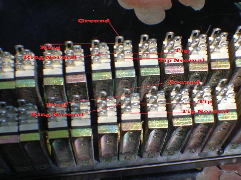
-Bob
-
 Thick or Thin wire?How thick or thin should wire be?Johnny Don't!On May 23, 2016, at 12:20 PM
On May 23, 2016, at 12:20 PM, Johnny Don't!
Wow, what a great website you have! I will probably be purchasing one of your 1/4" TRS solder-point bays very shortly.
My question is regarding wiring a patch bay: what brand & gauge of cable should I use for the rear connections on a solder-point patchbay? I've done A LOT of research on this, and all of the info & images I've found demonstrate a rather thin cable on the back of the patchbays. I've always heard thicker cables are best for audio purposes, so I want to be sure I'm using the proper cabling in my patchbay.
Thanks in advance for any advice or information you can provide.
Long days & pleasant nights,
Johnny Don't!
____________________________________
Hey kids, don't do what Johnny Don't did!
https://www.facebook.com/airthissideofcaution
www.facebook.com/johnnydontmusic
Hey Johnny,
That is a matter of opinion. ADC patchbays shipped with 22 AWG cables. However some thoughts are the thinner the wire the better the sound. Mogami is very thin and sounds very good.
In fact some folks use only one in wire for audio: http://shop.mapleshadestore.com/Interconnects/departments/86/
Please remember that your audio signal path is only as good as the weakest link. So all components and cabling should be equal in greatness.
Sincerely,
Bobby Hickey
817-926-9535
-
 Patchbay HelpToft Audio 32 ATBCarlosOn May 16, 2016, at 10:34 PM
On May 16, 2016, at 10:34 PM, carlos **************
toft audio 32 channel desiggns series atb
orion 32 sound card
priamps:
portico ii rupert neve
avalon 737
manley vovxbox
universal audio 6176
hey Carlos,
Here is a patchbay layout I made for you: https://www.misterpatchbay.com/Patchbay-Carlos.htm
Here is the type patchbay I would suggest: https://www.misterpatchbay.com/patchbays/mini-shorti-quick-switch-patchbay.html
The advantage I offer over all other Pro Audio dealers is: The others only sell patchbays with DB-25 FEMALE connectors on the rear of patchbays. Meaning you must buy 12 eight-channel DB-25 snakes for each 96 point TT patchbay. Depending on what type eight-channel snakes you buy that cost $600 to $1,000.00 for each 96 point patchbay to get wired-up.
On the other hand I offer cables that are hard-wired to the back of the patchbay jacks with whatever type connectors you need. So when your patchbay arrives from Misterpatchbay you just plug and play. Hell yea…
Sincerely,
Bobby Hickey
817-926-9535 -
 First Time BuyerFirst time patchbay buyer who needs some guidanceMICHAELOn Apr 14, 2016, at 5:30 PM
On Apr 14, 2016, at 5:30 PM, MICHAEL
Hi,
I want to get a patchbay for my studio. Instead of buying an expensive multichannel audio interface, I decided to get a good quality one with a few channels, and hook it up to a patchbay so I can access outboard gear as I need it. The interface I decided on is an Audient ID22, which has 2 xlr/trs mic/line inputs and 6 outputs. One set of outputs would go to my monitors. It also has 2 sends and returns that I can use to hook into outboard gear, which is perfect for the way I want to work. I only record one thing at a time. This box would let me do that and still keep a stereo compressor on my mixbus. https://audient.com/sites/default/files/id22-manual_v1.8_en.pdf
So I want to hook that into a patchbay. The outboard I need to hook into the patchbay is as follows:
3x 2-channel preamps and 1x mono preamp, each with one XLRmic and one DI input per channel
4 channels worth of compressors that can use either XLR or TRS
1 mono EQ that can use xlr or trs
I also have 7 effects units, delays etc that would be fun to hook in as well. They are all TRS or TS.
I’m trying to learn about normals, halfnormals etc. and I’m understanding it but it’s hard to wrap my head around exactly the way I should have the patchbay set up. I don’t want to get into soldering, and it looks like you have options in your store that would keep me out of the soldering arena.
I just want a way to easily patch preamps and outboard gear in various combinations and send it through the Audient when I’m tracking, and to use my outboard as inserts when I’m mixing/ adding effects.
What would you suggest?
Thanks so much for your help,
Mike
On Apr 15, 2016, at 8:42 AM, Bob Hickey
Thinking of your setup. I would do something like this:
top-row
( Audient outs) (Audient insert sends) (mic press out) ( comp/limiters out) (EQ’s out) (effects out) (any mastering stuff outs) (MULT ONE)
bottom-row
( Audient ins) (Audient insert returns) (mic press inputs) ( comp/limiters inputs) (EQ’s inputs) (effects inputs) (any mastering stuff inputs) (MULT TWO)
you may have more outputs than inputs. so you end up with some blank hole in the patchbay so that in’s & outs can line up top & bottom. I will explain MULTS later tonight or you can google that.
Bob
On Apr 18, 2016, at 2:52 PM, MICHAEL
Bob,
I had a busy weekend and wasn’t able to get my head around MULTS but will do so over the next couple of days. I understand the rest of the recommended setup (outs/sends on top; ins/inserts on bottom). I will continue filling in the spreadsheet. Do you want me to send it back to you afterwards and take it from there?
Thanks,
Mike
Yes Mike please send the spreadsheet back when you are done.
MULTS: These are only a way to split signals. A four-way MULT gives you one input and three outputs. So you could take a mono audio signal and plug that into a MULT then you can send that signal to two ( or three) different signal paths using different comps , EQ or other effects and then A/B the two signals. Or works great to make a mono into simi-stereo etc.
-Bob
-
 Half NormalsHalf Normals for Audio Accessories Longframe>DB25GregoryJanuary 28th, 2017
On Dec 2, 2015, at 1:12 PM, Gregory *************
Greetings,
I'm trying to reconnect the normals on an Audio Accessories Longframe>DB25 bay that is wired straight thru-no normals. I've only done punchdown ADC types- The back of the jacks on the top row have 3 solder lugs - while the bottom row has 5. Which I assume limits my options to half-normal only. I attempted a photo but it's a bit crowded in there so I've made a diagram looking at the back of the jack
lugs. I posted a question on GS - and a kind person said that all I would have to do was to move the two wires (G & H) to the open lugs (E & F) on the bottom jack. (after determining which is tip and ring with a continuity test)
However- I was under the impression that, assuming that those two unused lugs on the bottom row jacks are the tip-normal and ring-normal - I would have to solder the top row tip to the bottom row tip-normaland the top row ring to the bottom row ring-normal?
Obviously moving the two wires up to the open lugs sounds A LOT easier! I can leave most of the pretty shrinkwrap in place! Could you tell me the proper (easiest) way to get this half-normalled?
Thanks!
Greg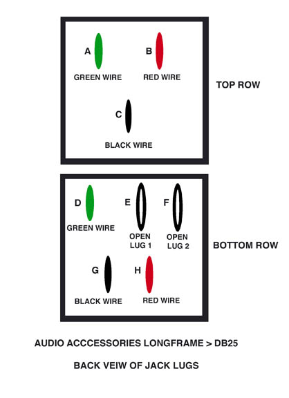
On Dec 2, 2015, at 1:47 PM, Bob Hickey
Hey Greg,
Yes that patchbay can only be wired no-normal or half-normal. To wire half normal solder jumper wire(s) from F to B that will be the tip ( hot). Then wire from E to C. If you have an ohm meter that would be the best way to test your connection on channel #1 BEFORE you wire the whole think and find out it’s wrong.
With you ohm meter touch the tip inside the jack and touch H and then F. They should both have contact. Now plug a patch cable into the channel. While the cable is plugged-in touch the tip of the patch cable and touch H & F again. With the cable in H should still make contact while F will not. Do the same with G & E.
Sincerely,
Bobby Hickey
817-926-9535
On Dec 3, 2015, at 10:38 AM, Gregory *****************
Thank you so much Bobby, I did exactly what you said- and presto! We're half-normal! - It's really tedious work - I did 4 channels before deciding to unscrew the rear frame holding the DB25's which gives me a bit more (not much) room to work. I'm assuming there arent any shortcuts ….or are there?
Again, I needed this for an important project that's mid-stream and you saved me at least 3-4 days of downtime. Again, MANY Thanks!
Sincerely,
Greg
No problem Greg. No short-cuts known.
Bob -
 Vertical StrappingI have a question about vertical strappingChristopher WeingartenOn Oct 14, 2015, at 9:40 AM
On Oct 14, 2015, at 9:40 AM, Christopher Weingarten
I have a pre-wired switchcraft patchbay with bussed grounds for every 8 patch points. I do not have a board. I am using individual pres and will want to run phantom from the mic tie line normalled to the mic pre ins. I was told to have these patch points vertically strapped. Switchcraft told me that I just need to snip the ground wire that busses all 8 and solder (or gator clip) a lead between the ground pin of the top point to the one right below it. Is this absolutely all I have to do or do I need to send the ground anywhere else from there?
If you have any other info that I would need to do this on my own please let me know. Your help is much appreciated.
Thanks!
-Christopher Weingarten
Musician
Recording / Mixing Engineer
Hey Christopher,
Switchcraft told you correctly. Snip the strapped grounds that go from channel to channel. Then just solder a wire from the ground on the top-row to the ground on the bottom-row below it and you will be GVS. That is all that is needed.
Bob
On Oct 14, 2015, at 3:09 PM, Christopher Weingarten
Thanks Bob! Really appreciate you helping out a stranger!
No problem. -Bob
On Oct 14, 2015, at 6:21 PM, Christopher Weingarten
One last question. Once each channel is GVS do those individual grounds need to be touching some part of the chassis? Where do the vertically strapped grounds actually ground to? Since the main objective for this is to pass 48V phantom from mic pres to mic I just want to make sure i don't run into any danger. Thanks again
-Chris
Hey Chris,
Ground (pin 1 on your XLRs) will be provided to the patchbays’ ground pin by the input on your Mic Pre via the GVS that ties the two patchbay rows together. Then the GVS will send that ground from the MicPre through the patchbay to your microphone. Phantom will pass down that same ground wire. All will be good.
Bob
On Oct 14, 2015, at 7:33 PM, Christopher Weingarten
excellent! Thank you again! -
 How to route a patch bay?I’m trying to wrap my head around how to route a patch bay.Scott McOn Oct 11, 2015, at 8:51 PM
On Oct 11, 2015, at 8:51 PM, Scott McC*********
Hi,
I’m trying to wrap my head around how to route a patch bay. If I want to run my 8 mic pre’s on my PreSonus Studio 192 (which is my audio interface) into the patch bay, I just can’t figure out how that is going to work. If I run the first 8 in’s on the patch bay to the in’s on the Studio 192, how and where would I plug in my microphones ? And do the outs run to the 8 outs on the Studio 192. Wouldn’t that take up number 1 and 2 where I would normally put my monitors ?
What I’m trying to accomplish is to use my outboard gear by using the patch bay. I have a reverb, compressor, and eq that I would like to put on the patch bay, and be able to say use my mic #1 input on the Studio 192, and patch it into say the outboard compressor, and back into the interface.
I think I have it figured out, and then I realize that I still don’t understand all of it. I have pretty much got normal, half normal and through, into my brain, but still can’t wrap my head around how to route everything.
If you could just steer me in the right direction I would be so grateful. I have scoured the internet for information, but still haven’t succeeded.
Thank you for taking time,
Scott
—————————————————————————
Hey Scott,
If you look at this layout: http://www.misterpatchbay.com/Patchbays-for-Ryan-1.htm
you may see that by using normals, the client can plug-in a mic in the studio and that mic goes directly, via normals, into a mic pre (by using a patch cable he can send the mic to a different mic pre). Then the mic pre out goes directly , via normals, into his Symphony inputs and the Symphony outs , via normals, go directly into his ToneLux summing mixer. He can insert any effect into anywhere in the signal chain. We do not use normals for effects, comps , reverb etc..
See how this works?
Bob
-
 iPhone to TTHow Do I Hook my iPhone to a TT Patchbay?Robert FrostOn Aug 19, 2015, at 6:12 PM
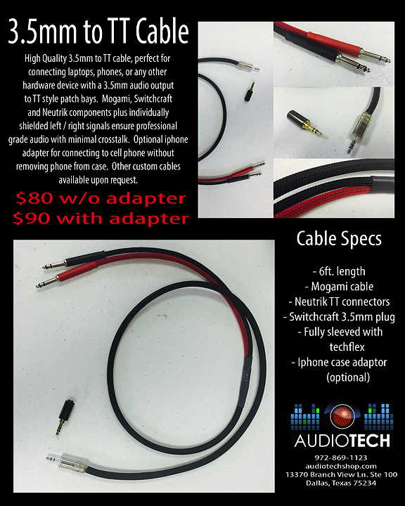
My friend Harley, the best audio tech in Dallas, has a new cable that is perfect for patching in your iPhone or iPad to a Studio's TT patchbay
-
 Phantom Powered MicrophonesWhen we use phantom powered microphones, we experience a significant loss of signal, as well as some noise.JustinOn Mar 11, 2015, at 2:11 PM
On Mar 11, 2015, at 2:11 PM, Frew, Justin
Hi guys... We are using an ADC brand bantam TT 96 point patchbay. When we use phantom powered microphones, we experience a significant loss of signal, as well as some noise. Also we can’t seem to get a decent amount of signal through our external pre as well (Universal Audio 610). When bypassing the patch bay and panel ties, we get signal just fine. The patch points are fully normalled for convenience, however when using condenser mics, we need to manually patch through the normal for us to even get a weak signal...
Very strange, I Know!
Just wondering, have you guys ever experienced patchbay users encountering these kinds of issues where phantom power is involved? We are continuing certain tests to rule out exactly where the issue is stemming from, but thought it might be useful to pose the question to you guys as well. Please do let us know if you have any information regarding this.
Thanks and best wishes,
Justin Frew
Audio Technician
jfrew@aii.edu
P 778.373.8993 C 778.846.2291
2665 Renfrew St. / Vancouver, BC V5M0A7
artinstitutes.edu/vancouver
Hey Justin,
There is no “we” here sir. Just me… Bob Hickey - Mister Patchbay. Anyway your problem is that your ADC does not have the grounds normal from the top-row to the bottom-row. The standard ADC normal has only the tip & ring normal. Therefore your Phantom mics are not seeing any ground. That’s why when you use a patch cable it works correctly because the patch cable is connecting the ground from the top-row to the bottom-row. There are three ways to correct this.
1. Strap all grounds together.
2. Strap the grounds from the top-row to the ground posts on the bottom-row for each mic channel.
3. Send the patchbay to me and I will fix that for a small charge.
Sincerely,
Bobby Hickey
817-926-9535
On Mar 12, 2015, at 6:03 PM, Frew, Justin
Bob Hickey, you are the man!
It all makes sense now! I believe that the problem is that I didn’t normal the grounds.. Doiiii!
Thank you very much for your help, you are a life saver. I’m going to go with option 2 J
Thanks and best wishes!
Justin -
 Got something very simple?Have you got something very simple for me in stock? Db25MatteoOn Nov 3, 2014, at 1:30 PM
On Nov 3, 2014, at 1:30 PM, Matteo Bernacchi
Hi, I would like to buy Teac patchbay.
I just would like to know if you provide db25 to xlr M and db25 to xlr F cable snakes.
Waiting for your kind feedback
thank you
regards
Matteo Bernacchi
Those patchbays are sold out. Sorry. I will mark that on my website.
Sincerely,
Bobby Hickey
817-926-9535
On Nov 3, 2014, at 3:18 PM, Matteo Bernacchi
Hi Bobby,
Have you got something very simple for me in stock? Db25
Il lunedì 3 novembre 2014, Bob Hickey
Hello Matteo,
I can custom build a patchbay for you with whatever connectors you want: https://www.misterpatchbay.com/patchbays/adc-48-trs-db-25-patchbay.html
Bob
On Nov 3, 2014, at 4:07 PM, Matteo Bernacchi
Thank you Bob,
one other question: is there something available like 16 or 24 input / 16 or 24 output? Could you send it already soldered with xlr f and xlr m cables?
Matteo
That depends on what type of connectors your gear has. If you stuff is DB-25 then that’s the way to go. However, if your ins & outs are XLR then get me to solder XLR male & female connectors to your patchbay snakes because you do not want to buy six eight-channel DB-25 to XLR snakes…
Bob
On Nov 3, 2014, at 4:22 PM, Matteo Bernacchi
What's the best solution in terms of value for money?
db25 or direct soldered xlr's?
That’s cool. Yea… you can just list the number and type of connections and I will build you a patchbay with four-foot snakes that will match your gear. Then when you get your patchbay, you can just plug n’ play and get back to making music.
Bob
On Nov 3, 2014, at 5:03 PM, Matteo Bernacchi
I got XLR balanced equipment for the most part,
sorry for my apparent dumb questions, I just want to get a deeper and torough understanding of patchbay connections, in order to let me choose the best solution
On Nov 4, 2014, at 7:26 PM, Matteo Bernacchi
Hi Bob,
thank you for your patience.
• how about this one?
nice patchbays. I have five of those new in boxes but not yet on website.
• 52 point means 26 input and 26 ouputs? is it right? That should be good for my needs.
26 in and 26 out. That is correct.
• I would need snakes with all XLRs except 2 inputs jack trs and 2 outputs jack trs (dbx 166)
no problem.
• Let's see if i did my homework: does "normal" means every point on top row is permanently connected to corresponding bottom row until a patch cable is inserted top or bottom?
yes, correct.
please kindly let me know about these points.
sorry for my poor english, is the best you can get from an Italian guy.’
you speak english very well. You should read some of my emails…
-Bob
On Nov 5, 2014, at 8:29 PM, Matteo Bernacchi
Thank you Bob let's go ahead, how about money?
Hey Matteo,
I understand top-row all XLR-FEMALE but the last two are 1/4” TRS. The bottom-row all XLR-MALE but the last two are 1/4” TRS. Do you want full normal or no normals?
You can order the patchbay on the link below but, I will use the PJ-390 style that you like shown in the picture below.
Order here: https://www.misterpatchbay.com/patchbays/adc-48-trs-db-25-patchbay.html
If you want me to build this using a new ADC PJ-390 patchbay, next after you order the custom patchbay with the link above then select "continue shopping" and use this link to upgrade for $65.00 to the new patchbay: https://www.misterpatchbay.com/patchbays/adc-48-trs-db-25-patchbay.html
Sincerely,
Bobby Hickey
817-926-9535
-
 Audiolot MixBayHere you can add a short description for your article, something to grab the users attentionDylanSep 29, 2014, at 12:25 AM
On Sep 29, 2014, at 12:25 AM, Dylan
Hi, I’m a project studio owner who is just starting to accumulate enough outboard gear to justify tidying things up with a patchbay. Only problem is that I can’t get my head around them haha I’ve read a number of tutorials, but I figured the best way to comprehend what I need is to just tell someone like you my exact situation …
My chain looks like this:
DAW – MADI cable –> Converter with 16 I/O over 4x Dsub – Analogue cables ->
In my outboard rack I have a 500 series chassis with 10 I/O on XLR, but a second set of ALT I/O for every module
I also have numerous single and dual channel processors and pre-amps.
I use RME Totalmix (powerful digital mixer with virtual routing).
Now what I want to be able to achieve is have a tidy front panel for connecting source inputs, such as microphones or instruments, then have everything interconnected such that I can see and route any I/O anywhere using Totalmix routing. I have a feeling the AUX I/O for the 500 series modules will be crucial to having a front panel wired for mic inputs as well as the ability to feed other outputs to the module so digital routing is possible.
Do you think I only need a pass-through style bay or am I dreaming?
If I’ve been clear as mud, here is a thread with a more specific rundown, except in this email my 500 series rack example has 2 sets of I/O on XLR instead of 1 set on Dsub.
Cheers
Dylan
Hey Dylan,
No problem. It's about 2 am here and my brain is not working anymore tonight. I have lots of international shipping to take care of tomorrow day. However, I will take this matter up tomorrow afternoon or tomorrow night and get back with you.
Sincerely,
Bobby Hickey
817-926-9535
On Sep 29, 2014, at 6:44 PM, Dylan
Thanks, mate. I’ve actually contemplated getting a Skype subscription in order to be able to just call to the US, but the time zones make it difficult.
The Audiolot MixBay (192pt) has been suggested to me as a good solution, but it’s out of my price range, especially after adding cables.
To break it down, what I want to be able to do with the patch bay is:
Have all 19” outboard and 500 series modules connected to the converter I/O, such that they are normalled on the patchbay, so I can “chain” together any combination to be routed as a single insert within my DAW (or Totalmix). I also want to be able to plug any source (ie mic) into the patchbay due to its convenient front of desk location. Finally, I want to have my 32 channel summing mixer connected in such a way that I can both route converter outputs to it AND be able to insert any of the above outboard onto any channel, especially the 2 bus.
On each floor rack, I will eventually end up with around between 16 and 22 channels of outboard. The converter in each rack is 16 channels, so I may add a second (to a total of 4) as my outboard approaches the 8 or so mark per rack.
I have the option of putting the patchbay on my mixing desk, which sits between the two floor racks. This could be done, if necessary, to facilitate normalled patching across any unit in either floor rack, but I guess I’d rather have one patchbay per rack if I could find a way for it to make sense to do so.
Sorry if I’m vague/misguided. It’s my first venture into patch bays as I have always done everything within my DAW until now.
Cheers,
Dylan
Hey Dylan,
Game 7 of the Baseball World Series seemed to be a good time to work on your project before I go back to soldering connectors. It’s 3 to 2 in the ninth!
here is what I have so far: http://www.misterpatchbay.com/patchbays-dylan.htm
Bob
On Oct 29, 2014, at 10:28 PM, Dylan
You’ve done this a few times before, haven’t you? Haha I’m going to need to check it out on my home computer as the entire layout would take about 20 of these low resolution monitors at work to fit it haha Also, patchbays are new to me, so it will take a while of following things around before it sinks in.
I’ll get back to you as soon as I can. Again, much appreciated!
Cheers,
Dylan -
 Two 500 series enclosuresI have two 500 series enclosures on my deskLesOn June 23, 2014, at 1:39 AM
Hello,
I have two 500 series enclosures on my desk, right now I'm using 16 channels for them. They are about 6 feet from my rack. I could move them to the other side of my desk if that would save money but in their current position, I would probably need 8 foot runs to make it to the patchbay without stretching etc.
4 channels from them (mic pre's and 2 compressors) go to the Avid Omni which accepts TRS in. The Omni has DB 25 out but only TRS back in.
I would prefer to run the Bricasti as AES/EBU but the omni only has DB25 AES/EBU out so I would be using an entire snake for just one connection. Is it possible to have an AES/EBU DB 25 cable with just one connection? Here's the rear view of the Omni
http://cdn1.gbase.com/usercontent/gear/3123542/p5_uwmix1x4i_so.jpg
The Sta-Level, Clariphonic and Bricasti are rack mounted in the same rack as the patch bay would be.
It is a 14 space slant rack.
I would like to be able to freely patch eq's, comps etc in series or even paralell if possible.
I have listed most of my gear below.
I am also wondering what the best way would be to get microphone input to the 500 series preamps.
They are able to be used as a mix bus and I will be sending stuff to them during the mixing stage to use the EQ sections of them.
What would be the easiest way for me to switch between microphone input and input from my converters? It would be great to have
Avid Omni
Lynx Aurora
Rear view
http://www.audiolot.com/proaudio/sales/lynxstudio/images/aurora16/fullsize/aurora16-rear.jpg
purple audio sweet ten rack with
Crane song Falcon x 2
Retro Doublewide x2
Moog 500 Delay x2
Elysia nVelope
Kush Electra x2
Moog Laddder
AWTAC channel comp 2
AWTAC Channel Pre X 2
Retro Sta-Level - mono
Kush Clariphonic - stereo
Bricasti M7 (can be AES/EBU or analog)
Hughes SRS (takes RCA in and out)
Thanks so much.
Les
Hey Les,
Yes I first had the first 16 channels on the top-row as 16 mic inputs but, you said you only use a total of four. So I put the Lynx outputs on the first 16 channels on the top-row and placed your four mic inputs as 45-48 on the bottom-row. Please check this version: http://www.misterpatchbay.com/Patchbays%20Les2.htm
Well the signal flow is up to you. I made what I think would work for me. Any channels that are "Full Normal" are connected from the top-row to the bottom-row without the need for a patch cable. Then if you want to over-ride the normal, you just place a patch cable into that hole and the normal stops and the signal from the patch cable is sent to whatever device is wired to the back of the patchbay on that channel.
Bob -
 Using Mogami 2549Could you explain the differences?GeorgeOn June 23, 2014, at 1:34 AM
Hi there!
I am putting together a home studio and need a patch bay. I will have about 6 to 8 full normal, the rest will be no normals. I am thinking the solder type patch bays.
Could you explain the differences between the 1RU Switchcraft 96 point TT Patchbay and the New 2RU ADC 96 Point TT and your recommendations for me.
I'm thinking of using Mogami 2549 to wire the patchbay to the equipment because it seems to be the best. Any recommendations on wire would be greatly appreciated also.
Thanks!
George
Hey George,
Well sir, the 1RU SwitchCraft with large labels is out of stock. Not sure when I will get more. I do have one ADC with large labels in stock. I do not have any pictures of the one with large labels yet but, it could be ordered here: http://www.misterpatchbay.com/patchbays/whirlwind-96-point-tt-patchbay.html
The new 2RU ADC has seven solder lugs and is kinda hard to solder because there is not much room for working. The Mogami sounds great. Hard to beat the sound of Mogami without spending lots of money.
Sincerely,
Bobby Hickey
817-926-9535
Hi Bob,
That sounds good to me. I would like to order that. Should I call you now?
-
 TT Style PatchbayI would like to re-wire my patchbay to a TT style patchbayBradOn May 16, 2014, at 3:31 AM
I currently have mic lines coming into my control room with 1/4" trs male connectors soldered to each line.
I would like to re-wire my patchbay to a TT style patchbay.
Will the db25 style patchbays work for me? Can I cut and solder my current mic lines into a db25 male connector? Will that db25 connector allow for phantom power pass thru?
What do you recommend?
Here's my setup:
28 Mic Lines
24 xlr Mic Inputs TOFT ATB Console
24 1/4" trs Line Inputs TOFT ATB Console
24 1/4" trs Direct Outs TOFT ATB Console
24 Inputs Pro Tools HD 8x8x8 Native
24 Outputs Pro Tools HD 8x8x8 Native
8 Mic Inputs Focusrite 828
8 Line Inputs Focusrite 828
8 db25 Outputs Focusrite 828
4 xlr Inputs API 3124
4 xlr outputs API 3124
-------------------------------
Hey Brad,
Lots of different ways to go here. Looks like you will need two 96 point patchbays to contain all signal paths. How much soldering do you want to do? All of it?
Most of my patchbays are hardwired to the back of the patchbay. I see no need for you to make DB-25 connectors for your mic lines at this moment. The only place I see you need DB-25 is for your Pro tools in & out correct? And yes on Phantom Power thru DB-25's. We strap the grounds on the patchbays side for Phantom and the DB-25 knows nothing about it, it just passes the signal. Let me think while I finish off an order…
------------------------------
I'm trying to be lazy and avoid much soldering if at all possible. :-)
I would feel more comfortable with something like a mini shorty quick switch if I'm wiring it up myself.
I also have db25 outputs on the Focusrite 828.
I definitely would rather cut off the current 1/4" connectors on my mic lines and make a more stable connection.
What do you suggest?
------------------------------
Hey Brad,
If you want to go the Mini Shorti route then I think what might just work fine is you get one Mini Shorti with DB-25's and get one with E3 for all your mic lines and your 1/4" stuff. The E3 is a three-pin ELCO that is very flexible down the road. You can unplug any "one" channel and plug in a different wire with a different type connector if and when needed. And we all get new gear every few years...
Both these pages that show Mini Shorti's are showing 2RU. What I have in stock is 1.5RU. Even my Mini Shorti with DB-25 is a 1.5RU.
Here is an E3 Mini Shorti: http://www.misterpatchbay.com/patchbays/mini-shorti-quick-switch-e3-patchbay.html
Here is an E3 Mini Shorti shown wired: http://www.misterpatchbay.com/patchbays/mini-shorti-quick-switch-patchbay.html
The E3 mating connectors are easy to make. The video called "How to crimp gold E3 ELCO pins " on this page shows how to do it: http://www.misterpatchbay.com/patchbays/movies-how-to-wire-your-patchbay.html The only issue making E3's is the cost of the Bittree Crimp Tool is $185. Boo. However, I will loan you my Bittree Crimp Tool if you put up a deposit until you return the item.
Or we can do anything else you choose. Most guys these days have me build patchbays that already have cables and connectors so they can plug & play. Sounds like you have all the cables you need now.
Oh yea….! I forgot. I do have quite a bit of MOGAMI snakes with E3 connectors that I can let go pretty dang cheap. I sold like two snakes to a guy and forget which snakes those were at the moment… it's 3:19 am and going brain dead... but here is the list below that some of the snakes may match up with what you need…
MOGAMI 2938 Snake Cables
2 x 12FT 16 Channel TRS -> 16 Channel EDAC 3pin (E3M)
• 2 x 12FT 32 Channel TRS -> 32 Channel EDAC 3pin (E3M)
• 1 x 12FT 8 Channel TRS -> 8 Channel EDAC 3pin (E3M)
• 1 x 12FT 24 Channel TRS -> 24 Channel EDAC 3pin (E3M)
• 1 x 13FT 8 Channel TRS -> 8 Channel EDAC 3pin (E3M)
• 2 x 20FT 4 x DB25 -> 32 Channel EDAC 3pin (E3M)
• 1 x 35FT 16 Channel XLR F, 4 Channel XLR M, (12 Channel bare wire) -> 32 Channel EDAC 3pin (E3M)
• 1 x 12FT 8 Channel TRS Balanced, 4 Channel Send/Return TRS , -> 19 Channel EDAC 3pin (E3M), (5 Channel bare wire)
• 2 x 10FT 8 Channel RCA -> 8 Channel EDAC 3pin (E3M)
• 1 x 30FT 4 Channel XLR F, EDAC -> EDAC
• 1 x "Y" Cable: EDAC <- EDAC, 4 Channel XLR F (XLR's braided together) 8 Channel XLR M, EDAC -> EDAC
• 1 x 20FT 32 Channel bare wire -> 32 Channel EDAC 3pin (E3M)
-Bob
-
 Mini Shorti 1/4" TRSAudio Accessories Mini Shorti Quick Switch 52 PointSalOn May 4, 2014, at 1:21 AM
Hi Bob,
I got an Audio Accessories Mini Shorti Quick Switch 52 Point from you a
few months back and couldn't be happier with it! I'm looking to get
another patchbay and would like the same type, but I would need at least
32 ins and 32 outs on this one. You mentioned in a previous email that
you had a 48 points per row (96 points total) if I'm not mistaken, so
that would work. I couldn't find them on your webpage. Are they the TT
type?
I don't know if this is relevant, but it is for a 16 track setup to/from
a mixer to/from a tape machine. The tape machine has 96 point ZIF ITT
("DL") connectors (Cannon DL2-96R); one for inputs, one for outputs
(wired standard like the SSLs, but I will provide a diagram). I believe
the connector they would "mate" with is a "Cannon DL2-96P". I don't
remember what you said the max cable length was you could do, so I'll
just put what I would like for now. Ideally, I'd like something like
this:
TOP ROW:
1-16: 10' leads to female XLR
17-32: 4' leads to female XLR
33-48: 10' leads to single Cannon DL2-96P
BOTTOM ROW:
1-16: 10' leads to TRS
17-32: 4' leads to male XLR
33-48: 10' leads to single Cannon DL2-96P
Let me know what you think. I can give you a call to discuss details.
Thanks again and take care,
-Sal
--------------------------
Hey Sal,
Which sex do you need the Cannon connectors to be? One of each sex? I think I have some of those connectors in a box at my shop. Not sure if they are DL2-96R type or not. Do you know if the DL2-96R has 288 pins? Please let me see if I can find those connectors and then we can speak about a patchbay.
Bob
--------------------------
Hi Bob,
Sorry for not clarifying. The part number "DL2-96R" refers specifically
to the "female" connector, and the "DL2-96P" is the "male" connector.
There's a reference to the female connector standard pinouts here:
http://wwws.patchbays.com/pinouts.htm#120
The DL2-96R and DL2-96P connectors only have 96 pins.
Here's the company product page:
http://www.ittcannon.com/p/457/dl
Though the one pictured on the page is not the 96 pin version like I
need.
I would need both of them to be "female". They're like XLRs in that the
"female" version is not the one with the "pins" but rather the one with
the larger "plug".
If you don't have them or can't source them easily, then I think we
could just terminate those leads in a DB-25 or EDAC or something like
that and I could order a short custom adaptor from Redco that will make
the conversion. The other option is to just terminate them in male and
female XLR since the machine I'm hooking them up to can also use XLR,
but I'd like to avoid all those separate connections if possible.
Ironically the XLRs may actually be the cheaper way to go. Thanks again
and take care,
-Sal
---------------------
Hey Sal,
All my DL connectors are 120 pin. Boo. I can put DB-25 or XLR on the cables. I think I would go with XLR's and be done with it. That would be cheaper than getting DB-25's from me and paying for adaptors from Redco. I can put 16 XLR-M's on the cables, plug 'em in and away you go.
Bob
----------------------
Hi Bob,
You gave me a good idea of reusing my existing patchbay for this setup
so that I would only need one more 1/4" 52 point patchbay like the one I
have. If I could order 10' male/female XLR leads from you separate from
the patchbay, then I'd be able to retrofit my existing one with the
longer leads for the first 16 channels, and then order a second patchbay
for the next 16 channels and have 20 to spare. Let me know what you
think and I'll come up with a new configuration. Thanks and take care,
-Sal
--------------------
Hey Sal,
Good idea. That will work. That's the great thing about owning a patchbay with E3 connectors on the back! I'll make new cables and you just plug them in the patchbay you have… then we can add one more patchbay and that will be a done deal. cool eh?
Bob
---------------------
Hi Bob,
Yeah it really is! So this should give me what I need as far as
configuring the patchbay goes:
TOP ROW
1-16: 10' leads to female XLR
17-26: 4' leads to female XLR
BOTTOM ROW
1-16: 10' leads to TRS
17-26: 4' leads to male XLR
As for extra cables, I would need:
10 x 10' leads E3 to unterminated
16 x 10' leads E3 to male XLR
Thanks again Bob,
-Sal
-
 I found your site via ‘Gearslutz.’I’m looking to use a patchbay but have been given tones of different adviceOliverOn March 2, 2014, at 8:57 PM
Hi,
I found your site via ‘Gearslutz.’
I’m almost finished on the build of my new studio. I’m looking to use a patchbay but have been given tones of different advice on which would be best etc.
What I want to do is;
Carry signals (both line level and mic levee inc. phantom power) from my live room, to my control room via my 16 channel multicore (12in - 4returns)
Then have the option to patch into one of my pre’s or direct into my interface.
My interface only accepts 48v’s via XLR. ( I have the focus rite safari pro 40)
Below is a list of my gear. Could you possibly give me the best solution for what I would like to do and also give me a price on what I need etc??
Gear:
Focusrite saffari pro 40
Golden Age pre 73
Joe Meek Three Q
ART Voice Channel
ART MPA ii
Golden Age Comp 54
ART HeadAmp Pro 6
Thanks in advance
Oliver
------------------------
Hey Oliver,
There are a zillion ways to do this. Please understand that I do NOT sell 1/4" TRS patchbays that have standard 1/4" jacks on the front and the back of the patchbay. All those units are semipro and music stores sell them, not me. I only sell 1/4" TRS military-style, long-frame, B-gauge patchbays and TT ( tiny telephone) patchbays. TT patchbays are the same as the 1/4" TRS military-style, long-frame, B-gauge patchbays but are 1/8" jacks & plugs. So with the TT bays you get twice as many patch points. A standard TT patchbay has 48 holes on the top and 48 holes on the bottom for a total of 96 points. Most of the 1/4" TRS military-style, long-frame, B-gauge patchbay jacks have a duty-cycle of 50,000 inserts. And nobody puts a patch cable in a patchbay 50,000 times. Or if they do, those patchbays are not sold by me. Most of my patchbays are used but, still have decades of life left. I check & service all products I sell.
Another item of thought is long-frame 1/4" TRS B-gauge cables cost lots of money: http://audio-video-supply.markertek.com/search?w=1%2F4+long+frame+patch+cables I have new 1/4" long-frame patch cables that will be Mogami copies like the TT cables I sell and will be priced at about half what the Pro Audio dealers are selling for. However, the molds for the tips are just now being made and those cables are a month or two away from be here. My Mogami copies: https://www.misterpatchbay.com/patchbays/patch-cables.html
Looks like you could get this all in one 48 point long-frame 1/4" TRS patchbay but, one day as you add more new gear, you will run out of patch points.
If you want to stay 1/4" there are three models I would suggest:
1. Used ADC custom wired plug & play that has whatever connectors and normaling you need soldered to four-foot cables. The connectors can be standard 1/4" TRS or 1/4" TS (MONO), XLR or DB-25: https://www.misterpatchbay.com/patchbays/adc-48-trs-db-25-patchbay.html
2. Used Audio Accessories Mini Shorti Quick Switch TRS patchbay. This is shown with only DB-25 connectors but could have XLR & 1/4" TRS for $20 more. This style patchbay lets you change the normals with plastic shunts on each channel. https://www.misterpatchbay.com/patchbays/audio-accessories-52-pt-TRS-patchbay.html
3. Used ADC Punch-Down style long-frame 1/4" TRS patchbay. This is a do it yourself patchbay. It ships with no cables and you attach the cable to the rear of the patchbay on your own. Not hard to do but you will have to cut the ends off all the cables you war to use with this type patchbay. Nobody likes cutting their cables up. I always suggest clients buy one cable twice as long as they need and cut it in half and pouch the bare ends: https://www.misterpatchbay.com/patchbays/adc-pps3-18mkiino-patchbay.html or https://www.misterpatchbay.com/patchbays/adc-ppa1-14mkiins-patchbay.html
Normals: https://www.misterpatchbay.com/normaling/normal.html
TT patchbays: These are more patching than you need at this moment. But as I stated above, the cables are less costly and you can grow into this type bay. The cables, at least from me, are about half the price of the 1/4" TRS but the patchbays cost twice as much because they have twice the number of patch points. What I would suggest in the TT line:
1. Used ADC custom wired plug & play that has whatever connectors and normaling you need soldered to four-foot cables: https://www.misterpatchbay.com/patchbays/custom-50-50-patchbay.html
2. Used ADC Punch-Down style https://www.misterpatchbay.com/patchbays/adc-ppb3-14mkii-patchbay.html
As for how to hook a patchbay to your gear: I would bring all the studio lines into the first 16 channels of the top-row. The first 12 channels will need XLR-Females attached to the rear of the patchbay. Under those 12 mic lines on the bottom-row I would suggest having your Mic Pre's. That way the mic lines could be normaled to the pre inputs so you don't need a patch cable to make the connections but, you could use a patch cable to make changes such was if you wanted to send say mic #1 to pre #8 etc.
Then you compressors and other outboard gear can have their outputs on the top-row after the mic lines and the inputs below the outs. On your effects and comps you do NOT want any normals because this would send the outputs back to the inputs.
So that is kinda the main stuff, and I can answer more question or whatever you need after you get up to speed on the basics.
Sincerely,
Bobby
-
 Chilton MixerNeed Patchbay for Chilton MixerJamieOn Feb 24, 2014, at 2:54 AM
Lorem ipsum dolor sit amet, sapien platea morbi dolor lacus nunc, nunc ullamcorper. Felis aliquet egestas vitae, nibh ante quis quis dolor sed mauris. Erat lectus sem ut lobortis, adipiscing ligula eleifend, sodales fringilla mattis dui nullam. Ac massa aliquet.
-
 Chilton MixerNeed Patchbay for Chilton MixerJamieOn Feb 24, 2014, at 2:54 AM
Your Name: Jamie Your Email: **********@gmail.com Subject: RE Patch bay for Chilton mixer / long frame bantam Australia Message: Hi again, here is the real list of what's required for the long frame bantam patch bay - to hook up to the Chilton mixer: TRS inserts: 16 INSERT CHANNELS TRS balanced outs: 8 CHANNELS 12 x mono unbalanced Jack channel outs: 12 OUR CHANNELS 12 x mono unbalanced Jack line ins: 12 IN CHANNELS That's it really. So all would fit on 1 x 48 way long frame bantam patch bay, if configured correctly to a Dsub. Dsub breakout leads, or if you'd rather - you could make me a custom cable, but I don't know if you do that! Jamie :)
Hey Jamie,
I was making D-Sub connectors all night last night. Anyway, no problem building your project. The best way I think is for me to hard-wired cable to the patchbay and put to proper connectors on the other ends.
I can make your inserts with 1/4" TRS to plug into your insert on your console. I assume they are tip = send and ring = return. I have a large box with about 500 new MONO long-frame patchbay jacks that would be perfect for your project. All I would need to know is what connectors you want on the ends of the cables and how long the cables must be. Price for this patchbay and four-foot looms is $260.00. Please note that any cables over four feet will cost more money.
Also I would need a list showing what you want where, as shown below:
Top-Row.
1. insert send 1 (TRS)
2. insert send 2 (TRS)
etc.
17. MONO XLR FEMALE
Bottom-Row
1. insert return 1 (TRS)
etc.
17. MONO XLR MALE
Sincerely,
Bob
Hi Bob,
I'll try to draw up a spread sheet.
RE your "large box with about 500 new MONO long-frame patch bay jacks" - I don't need any of these ... I have looms already with these jacks attached - to run between a patch bay and my muiltitrack and outboard.
What I require is a 19" rack mountable long-frame patch bay. This patch bay needs to be wired to TRS (jack) and XLRs to plug into the Chilton.
Here is the manual for the mixer, if this helps! Am I making sense?
Jamie
-
 1/4" Bantam PatchbayI need the old 1/4" bantam style patchbay.RichardOn Feb 13, 2014, at 9:04 PM
Message: Hi there, I have an old Neve console and require more patch points for the studio I'm about to move into. I need the old 1/4" bantam style patchbay. I'm feeding the patchbay via db-25 connectors. I need approx. 36 points. Do you have anything currently available? Also needing 1/4" bantam patch cables. Hope to hear from you soon. Cheers Richard
Hey Richard,
Yes sir, however all the patchbays I have are standard 19" rack mount. If you need the smaller side-car type unit, I do not have.
I think you will find that what you are looking for is called B-Gauge, Military-Style or Long-Frame 1/4" TRS patchbays and patch cables.
What would work fine for you is one of these: http://www.misterpatchbay.com/patchbays/adc-48-trs-db-25-patchbay.html
Also if you are wanting to do the wiring, I have these: http://www.misterpatchbay.com/patchbays/adc-pj-390-patchbay.html
The only long-frame cables I have today are twenty that are four-feet long and do not have the red-plastic strain-covers. Price $5.00 ea.
The way to know if the cables are long-frame and not standard TRS is by looking at the tip of the connector. The standard has a heart-shaped tip and the long-frame cables have a ball shaped round tip.
The long-frame 1/4" TRS patch cables can be quite costly new:
http://www.bittree.com/long-frame-14-patchord-p-339.html
http://www.markertek.com/Cables/Audio-Cables/Audio-Patch-Cables/TE-Connectivity/DA1.xhtml
http://www.fullcompass.com/category/TRS-MT-Patch-Cables.html
Sincerely,
Bob
-
 Don't have the time…Don't have the patience/time/skills to work with the punchdown patchbayIsaacOn Jan 9, 2014, at 12:40 PM
Your Name: Isaac Your Email: isaac********@gmail.com Subject: sale/trade Message: hello. I have 3 adc 48 pt punchdown patchbays in relatively good condition. I am looking to buy patchbays with 1/4" I/O, just don't have the patience/time/skills to work with the punchdown. Wondering if I could trade/sell you the ones that I have and/or buy something that you have? thanks! Isaac
Hey Isaac,
Before you decide to go with the semipro 1/4" front & back please look at my "How to use the ADC Punch Tool" movie: http://www.misterpatchbay.com/patchbays/movies-how-to-wire-your-patchbay.html this is very easy to do and will not take long at all. Plus your signals will be going thru a Pro Audio patchbay and you will not lose any DB or top-end.
-Bob
On Jan 9, 2014, at 1:10 AM, isaac
Thanks for the helpful video!
I only have 3 12-headed TRS snakes, and I'd need at least 8 more of those, good suggestion for sourcing those?
cheers!
isaac
Hey Isaac,
Here is what i have in used snakes with 1/4" TRS on one end:
1. Horizon 8 channels 18-feet
2. Canare 12 channels 23-feet ( I can cut this in half or in third's or less and solder more TRS connectors on the shorter snakes)
3. Canare 12 channels 23-feet ( I can cut this in half or in third's or less and solder more TRS connectors on the shorter snakes)
4. Eurocable 8 channels 24-feet
5. Eurocable 6 channels 24-feet
6. Audio Frequency 24 channels 4-feet
7. Belden 10 channels 11-feet
Bob
-
 Help needed for TRS InsertsI am currently wiring up an entire bay to handle the insert points of my consoleMartinOn Dec 31, 2013, at 2:19 AM
Hello Mr. Patchbay,
i have a question regarding an issue im having w my punchdown bay, as this is my first punchdown, im not entirely sure if the issue im having is user error or something else.
i am currently wiring up an entire bay to handle the insert points of my console. the bay has been half normalled and appears to be functional. the jacks switch and disconnect as expected. Howeer, the issue i am having is on the insert return. Once the connection is broken, the channel remains silent.
ive tried re punching the connections, using different bays, one w the grounds busses one wo a ground buss, and the issue remains.
the bays normalling are wired per the instructions found on your site, and the connections to the console are wired on the T R S terminals, im not sure if im missing a different wiring setup for the returns as it seems more or less self explanatory but im out of troubleshooting ideas.
i would tremendously appreciate any sort of help or insight you could offer. thank you very much.
Martin
Hey Martin,
An easy way to show you how to wire this, instead of trying to trouble-shoot your wiring, is to point you to a page on my site where I show how a TRS insert bay is wired: http://www.misterpatchbay.com/patchbays/quick-switch-trs-insert-patchbay.html
If your ADC QPC punch panel has the normals brought out to the remote ( orange and blue rows) then set one channel to full normal for this test. If not forget that and keep going as said below:
The send of your console TRS is coming out of the deck from the tip of the TRS. Wire that TIP to the HOT of the top-row ( red). Wire the return (comes from the ring of the TRS) to the TIP
of the jack on the bottom-row again this is the red QPC. Now take the ground and wire that to the white ground QPC on either row. Next take a jumper-wire ( scrap wire) and punch on top of the first ground wire, yes now there are two wires tall in one QPC. Take the ground wire and go to the other row and punch it into the white ground. the bald row for ring is not used. However some people wire for VSG vertically strapped grounds and wire the two ring common with the ground. Too much work and no difference.
So when you have the TRS inserted but no cables in the patchbay the full normal or the half normal will complete the loop. Then from the top-row of the bay you can send to a device with a patch cable and the output of your device goes back to the ring of the TRS by plugging a patch cable into the bottom-row. Dig?
If still confused or having more problems please do email again!
Sincerely,
Bobby Hickey
817-926-9535 -
 Mini Shorti Patchbays for the Wounded Warrior ProjectCables for the Wounded Warrior Project Music TherapySgt. GrearOn Dec 9, 2013, at 1:41 AM
Hello Bobby,
This is an email as requested to remind you of your contribution of the Audio Accessories Mini Shorti Quick Switch Patchbays and Patchbay cables for the Wounded Warrior Project Music Therapy
and The National Association of American Veterans.
- Sgt. Grear
Hello Sgt. Grear,
Your patch cables are on the way to you sir. Stay warm in this weather sir.
Sincerely,
Bobby
Wow-
Thank you much.
-
 Phantom PowerHow should I wire the ground for full normal patchbay with lots of mic input (phantom etc)?PeronOn Nov 22, 2013, at 12:18 PM
How should I wire the ground for full normal patchbay with lots of mic input (phantom etc)?
Thanks
Hey Peron,
Just connect all the grounds together.
-Bob
Bob,
I thank you very much for your helpful and fast reply. I hope with can do some business soon and you are welcome to Brazil
-
 Custom PatchbayLooking for a specific patchbayXanderOn Nov 21, 2013, at 9:18 PM
Message: Hi! Im looking for a specific patchbay i need and was wondering if you could help me out. here is what im looking for: - Simple pass-thru style (i.e bringing jacks from back of rack to front - rear jacks 1/4 inch (prewired breakout or just the jacks) - front jacks tt style let me know if this is something you have and the cost! thanks!
Hey Xander,
I can make a 96 point TT on the front and 1/4" TRS Male Plugs on snakes attached to the rear of the patchbay. This patchbay can be 2RU with large-lables or 1RU with smaller labels. I can build this for $526.67. If you want to buy, email me back. If you need longer cables than the standard four-feet, let me know.
That patchbay is here: http://www.misterpatchbay.com/patchbays/custom-tt-to-trs-short-cables-patchbay.html -
 Church Sound System & RecordingWe are in need of Patchbays for Church Sound System & RecordingMichael MazzottaOn May 15, 2013, at 11:29 AM
On May 15, 2013, at 11:29 AM, Michael Mazzotta
Hey Bob: it was great to speak with you today! Thanks for the conversation and down to earth advice!
Here is the set up:
Feed-
Room is currently feed 24 Channels from an XLR stage split
Converters: 24 in 24 out capability-
2 Digidesign 192 i/o converters = 24 In & 16 out (will soon expand additional 8 out) Multiple db25 connections here in divisions of 8
Passive Summing Mixer-
Roll Music FOLCROM passive summing mixer db25 16 in to stereo pair summing. This unit has no preamps in it to provide make up gain, the point of the units lack of pre is so you can put your favorite stereo preamps in line to provide coloration and style... I will neet to be able to put my variety of stereo pres in line with its output to get the line back up to volume in my DAW. Here is info on the piece if I'm not decribing this well... http://www.rollmusic.com/folcrom.php
Preamps-
(4 Ch) Daking mic pre 4= 4 instrument xlr ins, 4 xlr line in, 4 line xlr outs (will use
with folcrom)
(2 Ch) Chandler Abbey Road 2 channel= 2 instrument xlr in 2 line out (at
unity gain a line level is achieved will use with
Folcorm)
(2 Ch) Bae 1073 mpf= 2 instrument xlr in 2 line out (at unity gain a line
level is achieved will use with Folcrom)
(8 ch possible) Api 500 series lunch box= db25 or xlr with only 3 devices currently
installed. 2 pres and one compressor. The pres are a pair of BAE
312 api will use with Folcrom.
(1 Ch) UA Audio Solo 610= 1 Xlr in 1 Xlr out
(8 Ch) Digi Mic Pre= Db25 in Db25 out
(4 ch Art MPA) Xlr in Xlr out
Compressors-
Daking 2 channel stereo buss compressor= 2 Xlr in, 2 xlr Line in, 2 xlr line out
Inward Connections Brute 500 series compressor in Api Lunchbox (db25 or xlr
in/out)
Note- the system will eventually be built into a 24 in / 24 out system. There is currently a hum issue with the 24 channels coming in from the stage split... we have a transformer bassed split so im not sure what it is yet... if any of that could be resolved at the bay with grounding by all means let me know!!!
Thanks so much for your service to the audio community Bob: in the days of over charged corporate enterprise its AWSOME to have guys like you around who pick up a phone and take the time to help serve people!!!
--
Sincerely,
Michael
The Vineyard Church
www.TheVineyardChurch.com
Hey Michael,
The perfect patchbay for your setup would be the Audio Accessories Mini Shorti Quick Switch E3 96 point Custom TT patchbay. This patchbay will arrive ready to plug-n-play. But, can be changed in the future to meet your needs. That patchbay is here on the Audio Accessories website: http://www.patchbays.com/Shorti_quickswitch.htm
The Custom version from me is here: http://www.misterpatchbay.com/patchbays/mini-shorti-quick-switch-patchbay.html which I can mount DB-25 MALE connectors ready to plug into your gear. Plus I can solder 24 XLR FEMALES to accept your stage split. Then MALE & FEMALE XLR's for your mic pre's and compressors.
What I do on these is the patchbay has an FEMALE GOLD E3 connector on each channel on the back of the patchbay. Then I make, by hand, each cable that is an E3 to plug into the back of the patchbay and then the other end of each cable has whatever connector we need for your setup. This can be changed in the future quickly by unplugging any E3 and plugging in a different cable(s).
These patchbays offer the Quick Switch system letting you change the normal and or grounding on each channel. Great for live gigs where you are hunting-down the hum…
The patchbay can be setup a zillion different ways. One way might be this:
Patchbay Top-Row Patchbay Top-Row
1-24 XLR FEMALE accepts the snake split mic lines 25-48 192 Outputs via 3 X DB-25 MALE
Patchbay Bottom-Row Patchbay Bottom-Row
1-24 192 inputs normaled from 1-24 on the top-row to 3 X DB-25 MALE. 25-42 FOLCROM inputs via 2 X DB-25
43-48 mic pre's
If we took the FLOCROM inputs directly from the 192 outs we could free-up lots of channels. Because we still need to get all the pre's and comps into the bay. Well… let me make some coffee and think about this. We are running out of channels with only 96 points. Maybe we should use a second less costly 96 point solder-type patchbay hardwired to all mic pre's and comps etc.
Sincerely,
Bobby Hickey
On May 16, 2013, at 5:32 PM, Michael
Hey Bob... I sent them an update of our set up (listed below) and they won't give us any more information... Just said that after we purchase they will have one of their specialists explain how they will set it up for us. Ok thanks Bob!!!
On May 16, 2013 6:09 PM, "Bob Hickey"
:) Sounds like them. OK we will work this out. I will get on it tonight.
Here is a Excel layout I made tonight for you sir: http://www.misterpatchbay.com/Michael%206.2.htm
On May 22, 2013, at 11:16 PM, Michael
Looks great! Sending stereo L&R headphone mix out of protools to the FOH snake can work on this also? Super excited to get this!!! Thanks Bob!
I forgot to answer your question about the headphone feed back up the snake. If the headphone out from Pro Tools is a low-Z stereo feed then , no problem. If it is a hi-z 1/4" TRS stereo or two mono TS signals you can always stick the outputs into a DI( direct box) and then take an XLR(s) out of that to go back up the snake.
I am about finished soldering 24 XLR-F for the first 24 channels on patchbay #1.
-Bob
On May 27, 2013, at 8:53 AM, Michael
Nice!!
Hey Michael,
Here is your patchbay update sir: Patchbay #1 is finished. I installed 96 gold E3 connectors with 96 wires for bay #2. I am going to begin putting the connectors on all wires now for patchbay #2. Should finish up tomorrow.
Bob
On May 29, 2013, at 9:33 PM, Michael
Thanks!!!
-
 Transparent SoundIn your experience, do the other types (edac, db25, soldered) pass signal more transparently and less degradation/ crosstalk/ noise than TRS?ChrisOn Mar 13, 2013, at 3:15 PM
On Mar 13, 2013, at 3:15 PM, GUERICKE C RO***
Hi,
I'm interested in upgrading my patch bays. I currently am using the TRS format and have heard that Samson makes a decent trs bay. However, I am wondering if the sound is compromised using such bays.
Well sir, some of the semi-pro 1/4" to 1/4" patchbays loose .5 to 1 DB and some sound like they have a blanket over the high-end. I do not know and have never heard the Samson.
The only 1/4" patchbays I sell are the long-frame sometimes called military-style. They use a different type of 1/4" TRS patch cable. The tip of a long-frame TRS is round and not heart shaped. The jacks in the long-frame patchbays are much more robust. There is no signal loss and the top-end comes out the same as it went in. However they do not make 1/4" on the front and 1/4" on the back models like you can get in the semipro stuff. The used/refurbished 1/4" patchbays I sell all listed copse to $1,000.00 each when new. The reason they cost so much is they are very well built and will last a long time. The semi-pro 1/4" to 1/4" stuff is also know for making "noises" when they get a bit old and dust collects in the connectors.
On the other hand the semi-pro 1/4" to 1/4" patchbays may be better made these days than my last mixing dates. They are low-cost and you can just plug in and go.
In your experience, do the other types (edac, db25, soldered) pass signal more transparently and less degradation/ crosstalk/ noise than TRS?
The TT patchbays and the long-frame 1/4" patchbays sound the same. There is a little more surface contact with the 1/4" stuff which some people say is better for microphones. All the stuff I sell is rated for at least 30,000 inserts of a patch cable. Nobody EVER patches 30K times.
Of the non-rms types, which are most reliable over time? (knowing that straight wire and then soldering are the best connections) IOW, would DB25 be a good and reliable solution compared to punch down or edac?
The EDAC is very good but the standard now days is the DB-25. All the Pro Audio people but me sell all gear and patchbays with DB-25 FEMALE connectors meaning you must buy eight-channel DB-25 snakes. The custom patchbays I sell have any type connectors you choose even DB-25 MALE so you can plug right in your DB-25 stuff without buying D-SUb snakes.
Lastly, is there any sonic or reliability difference between switchcraft, arc, or Bittree?
None at all.
Thanks for your feedback.
No problem.
Sincerely,
Bobby Hickey
-
 How to Identify a patchbay?Could you help me with this information?StefanoOn Feb 27, 2013, at 6:05 PM
On Feb 27, 2013, at 6:05 PM, Dave Alvey <******@gmail.com> wrote:
Message:
Hi. I recently bought a couple of used patchbays as I want to move into a better connection than my old 1/4" Switchcrafts and Furmans are providing. Besides the pc cards on the Furmans are starting to fail here and there. So, I bought a pair of ADC 1U bays with the QCP punchdown blocks. They are both listed as cat# DAB307-4mkII. There are no normal/half normal provisions on the punch blocks but there is nowhere I've been able to find info as to whether these are internally normalled or not. I need not normalled for most of my situation with the outboard gear and the small Toft mixer and only a few normalled for the inserts. Could you help me with this information?
Thanks
Dave
Hey Dave,
The DAB307-4MKII would be a full normal I feel. The way to find out is to touch the red #1 and the red #25 with your multimeter set to ohms. If you have no multimeter, then open the top of the chassis by removing the four screws and four screws on the back of the chassis. If normal you will see a white-wire that is going from the top-row to the bottom-row on each channel. There will also be a black-wire that is going from the top-row to the bottom-row on each channel. These are the normaling jumpers. You can cut each of those wires to remove the normal and leave alone the channels you want normal. In the future if you want to re-normal those channels, strip back the wire's cover and twist together the two wires and dab with solder. Then cover with electrical tape or heat shrink.
Sincerely,
Bobby Hickey
-
 Testing ConnectionsWhat's a reliable way to test a patch bay? Is there an instrument I can buy at Radio Shack for instance?StefanoOn Feb 26, 2013, at 6:12 PM
On Feb 26, 2013, at 6:12 PM, Dean Landon
Hi Bob,
What's a reliable way to test a patch bay? Is there an instrument I can buy at Radio Shack for instance?
Thanks!
Best,
Dean
On Feb 26, 2013, at 5:25 PM, Bob Hickey
Hey Dean,
Yes sir, you need an Ohm Meter:http://www.ebay.com/sch/i.html?_sop=15&_sacat=0&_from=R40&_nkw=ohm+meter&rt=nc&_dmd=1
Bob
On Feb 26, 2013, at 9:58 PM, Dean Landon
Hey Bob,
Thank you for the info. As a matter of fact, I have one of those. What do I do to make sure the connections are correct?
Thanks again!
Dean
-----------------------
On Feb 26, 2013, at 9:21 PM, Bob Hickey
Hey Dean,
Select the meter to read ohms. Mine says 1K plus the omega symbol. If not sure or your reads differently, touch the two probes together and move your meters selector until the needle moves. That will be the ohms and show that to points are connected.
Bob
Hi Bob,
Is it just a matter of touch the tip and sleeve, or ring and sleeve?
Sorry, I don't know much about this.
Thanks again!
Dean
Hey Dean,
If you are metering a balanced connection, you would meter from tip to tip, ring to ring and sleeve to sleeve. Those should all be making contact. Then to see if something is incorrect, you can meter on one end if the tip is making contact with the ring or sleeve.
If you are metering a unbalanced connection, you would meter from tip to tip, ring&sleeve to ring&sleeve. Those should all be making contact. Then to see if something is incorrect, you can meter on one end if the tip is making contact with the ring&sleeve.
-Bob
On Feb 26, 2013, at 11:36 PM, Dean Landon
Thank you, Bob. As always, I appreciate your help.
Best regards,
Dean
-
 Advantages and disadvantages of normalsI'd like to know something more about the advantages and disadvantages of having these sets of patchbays - normalled - normalled with listen jacks - half-normalled - double-inneredStefanoOn Nov 29, 2012 at 9:44 AM
On Nov 29, 2012, at 9:44 AM, Stefano<***********@zmail.com> wrote:
Dear Bobby, first of all thanks for your quick reply. I still get confused on possible audio utilisations of these setups.
Is normalled better for insert-like situation or for send/ret?
in the usual configuration (output above the input) wouldn't it create a loop?
According to what you've written, it looks like the best situation to manage an insert point would be half-normalled, isn't it?
And I am still struggling to find actual "advantages or disadvantages" of these different setups. I mean, to me it sound like asking: what are the advantages of apples related to oranges?
Sorry for the last example!
Best regards.
Stefano --
On 29 Nov 2012, at 01:14, Bob Hickey
Hello Stefano,
I think the best is for you to look at my normals page:
I'd like to know something more about the advantages and disadvantages of having these sets of patchbays
- normalled
Advantage is: A normal keeps you from having to use patch cables to make the connections. When you plug a patch cable into either row the signal path is broken and follows the patch cable.
- normalled with listen jacks
These are for telephony commutations and are not used in Pro Audio that I have ever seen.
- half-normalled
Advantage is: A half-normal keeps you from having to use patch cables to make the connections plus since the top-row of jacks does not switch, you can use the top-row to make a "Y". So when the output of your 24 track recorder channel #1 is going to the top-row of a half-normal patchbay, and the first channel on the bottom-row of that patchbay is going into channel #1 line input of your mixing console we hear 24 track recorder channel #1 without a patch cable making the connection. Now we can insert a patch cable into channel #1 top-row of the patchbay and take that signal to a different channel on the bottom-row of the patchbay and patch it to a different channel of the mixing console. Now I can get two different sounds from one channel. I might send one signal to compressor type "A" and the other output of the 24 trk to a different compressor or EQ etc.. Now we can choose which sound we like the best or use both.
- double-innered
I have not ever heard that term sir. But a quick look on Google brought up this page: http://www.ips.org.uk/faq/index.php?title=Jackfield which says: "The words 'normalled' or 'innered' are used after the above. 'Innered' derives from the physical layout of the contacts. The contacts that connect to the plug are the 'outer' ones, these break away from the 'inner' ones."
I basically got the principles, but I can't understand which may be the relative (dis)advantages.
I hope that helps you. Please ask again if you are still not clear on normals. Good luck in that nice studio!
Sincerely,
Bobby Hickey
phone: 817-926-9535
Thank you very much.
All the best!
Stefano
-
 Toft Mixing BoardWiring a Studio with a Toft Mixing ConsoleMichaelOn Sep 15, 2012, at 12:06 AM
Hi Bobby,
Great talking to you today. I attached the new design with the 32 a/d d/a i/o's included. "patchbay2.pdf" shows the different rooms and how many channels come from each. The 24 channels from the N. Live Room, S. Live Room, and Iso booth are the ones that should be 'default' into the console. If we want to bypass the mic pre's in the Toft board and use outboard pre's we can patch in through the Line inputs on the toft. The 16 channels from the Barn Live Room, and the 6 channels from the Piano Live Room should 'interrupt' the signals from the other live rooms & iso booth (I think you called those "no normal" (??). We will add more outboard gear in the future that I assume can simply be patched in through line inputs or inserts.
I also included a diagram from Toft, of the input section AND the submaster and master section. Oh yes, and their 'star grounding' explanation that came with the manual.
The cabling I currently have is 4 each 12' snakes DB25 to 8 trs
I also have several DB25 to 8 xlr (female AND male)
Thanks!
Michael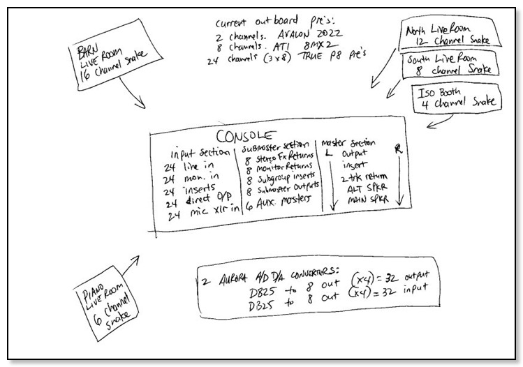
Hi Bob,
Here is the snake inventory:
(all these are 8 channel, and 8 to 15 feet long)
3 ea. TRS male ---- TRS male
3 ea. XLR male ---- XLR female
4 ea. DB25 ---- TRS male (I have one additional like these with molded ends for the "monitor hearback" system)
5 ea. DB25 ---- XLR female
2 ea. DB25 ---- XLR male
2 ea. 3' DB25 ---- DB25
1 ea. 6' DB25 ---- DB25
I forgot to mention that all the snakes in the studio coming from live rooms, iso booths, etc. need to be punch down as they have no connectors on them at present.
Thanks!
Michael
Hey Michael,
Here is a layout for all your great sir:
Bay #1 Top-Row has each snake punched to back of patchbay providing mic inputs.
Bay #1 Bottom-row has punched cables on the back of the patchbay to the mic inputs on the back of the Toft which will be MALE XLR:
Patchbay #1 Bottom-Row Channels 25-48 punched at patchbay with GROUND LIFTED. Other ends are TRS plugged into Toft Line Inputs
Bay #1 Top-Row Normal Type* Bay #1 Bottom-row Connector Type on Patchbay Your Snake Type to Toft
1. North Rm Mic 1 HN 1. Toft Mic input 1 DB-25 FEMALE #1 DB-25 Male to XLR MALE #1
2. North Rm Mic 2 HN 2. Toft Mic input 2 DB-25 FEMALE #1 DB-25 Male to XLR MALE #1
3. North Rm Mic 3 HN 3. Toft Mic input 3 DB-25 FEMALE #1 DB-25 Male to XLR MALE #1
4. North Rm Mic 4 HN 4. Toft Mic input 4 DB-25 FEMALE #1 DB-25 Male to XLR MALE #1
5. North Rm Mic 5 HN 5. Toft Mic input 5 DB-25 FEMALE #1 DB-25 Male to XLR MALE #1
6. North Rm Mic 6 HN 6. Toft Mic input 6 DB-25 FEMALE #1 DB-25 Male to XLR MALE #1
7. North Rm Mic 7 HN 7. Toft Mic input 7 DB-25 FEMALE #1 DB-25 Male to XLR MALE #1
8. North Rm Mic 8 HN 8. Toft Mic input 8 DB-25 FEMALE #1 DB-25 Male to XLR MALE #1
9. North Rm Mic 9 HN 9. Toft Mic input 9 DB-25 FEMALE #2 DB-25 Male to XLR MALE #2
10. North Rm Mic 10 HN 10. Toft Mic input 10 DB-25 FEMALE #2 DB-25 Male to XLR MALE #2
11. North Rm Mic 11 HN 11. Toft Mic input 11 DB-25 FEMALE #2 DB-25 Male to XLR MALE #2
12. North Rm Mic 12 HN 12. Toft Mic input 12 DB-25 FEMALE #2 DB-25 Male to XLR MALE #2
13. South Rm Mic 1 HN 13. Toft Mic input 13 DB-25 FEMALE #2 DB-25 Male to XLR MALE #2
14. South Rm Mic 2 HN 14. Toft Mic input 14 DB-25 FEMALE #2 DB-25 Male to XLR MALE #2
15. South Rm Mic 3 HN 15. Toft Mic input 15 DB-25 FEMALE #2 DB-25 Male to XLR MALE #2
16. South Rm Mic 4 HN 16. Toft Mic input 16 DB-25 FEMALE #3 DB-25 Male to XLR MALE #2
17. South Rm Mic 5 HN 17. Toft Mic input 17 DB-25 FEMALE #3 DB-25 Male to XLR MALE #3 You Must buy this DB25/XLR
18. South Rm Mic 6 HN 18. Toft Mic input 18 DB-25 FEMALE #3 DB-25 Male to XLR MALE #3 You Must buy this DB25/XLR
19. South Rm Mic 7 HN 19. Toft Mic input 19 DB-25 FEMALE #3 DB-25 Male to XLR MALE #3 You Must buy this DB25/XLR
20. South Rm Mic 8 HN 20. Toft Mic input 20 DB-25 FEMALE #3 DB-25 Male to XLR MALE #3 You Must buy this DB25/XLR
21. Iso Booth Mic 1 HN 21. Toft Mic input 21 DB-25 FEMALE #3 DB-25 Male to XLR MALE #3 You Must buy this DB25/XLR
22. Iso Booth Mic 2 HN 22. Toft Mic input 22 DB-25 FEMALE #3 DB-25 Male to XLR MALE #3 You Must buy this DB25/XLR
23. Iso Booth Mic 3 HN 23. Toft Mic input 23 DB-25 FEMALE #3 DB-25 Male to XLR MALE #3 You Must buy this DB25/XLR
24. Iso Booth Mic 4 HN 24. Toft Mic input 24 DB-25 FEMALE #3 DB-25 Male to XLR MALE #3 You Must buy this DB25/XLR
Bay #1 Top-Row Normal Type* Bay #1 Bottom-row Connector Type on Patchbay My Snake Type to Toft
25. Barn Mic 1 25. Toft line input 1 Cable Punched to patchbay 17 ft. Snake w/ TRS Connector
26. Barn Mic 2 26. Toft line input 2 Cable Punched to patchbay 17 ft. Snake w/ TRS Connector
27. Barn Mic 3 27. Toft line input 3 Cable Punched to patchbay 17 ft. Snake w/ TRS Connector
28. Barn Mic 4 28. Toft line input 4 Cable Punched to patchbay 17 ft. Snake w/ TRS Connector
29. Barn Mic 5 29. Toft line input 5 Cable Punched to patchbay 17 ft. Snake w/ TRS Connector
30. Barn Mic 6 30. Toft line input 6 Cable Punched to patchbay 17 ft. Snake w/ TRS Connector
31. Barn Mic 7 31. Toft line input 7 Cable Punched to patchbay 17 ft. Snake w/ TRS Connector
32. Barn Mic 8 32. Toft line input 8 Cable Punched to patchbay 17 ft. Snake w/ TRS Connector
33. Barn Mic 9 33. Toft line input 9 Cable Punched to patchbay 17 ft. Snake w/ TRS Connector
34. Barn Mic 10 34. Toft line input 10 Cable Punched to patchbay 17 ft. Snake w/ TRS Connector
35. Barn Mic 11 35. Toft line input 11 Cable Punched to patchbay 17 ft. Snake w/ TRS Connector
36. Barn Mic 12 36. Toft line input 12 Cable Punched to patchbay 17 ft. Snake w/ TRS Connector
37. Barn Mic 13 37. Toft line input 13 Cable Punched to patchbay 17 ft. Snake w/ TRS Connector
38. Barn Mic 14 38. Toft line input 14 Cable Punched to patchbay 17 ft. Snake w/ TRS Connector
39. Barn Mic 15 39. Toft line input 15 Cable Punched to patchbay 17 ft. Snake w/ TRS Connector
40. Barn Mic 16 40. Toft line input 16 Cable Punched to patchbay 17 ft. Snake w/ TRS Connector
41. Piano Rm 1 41. Toft line input 17 Cable Punched to patchbay 17 ft. Snake w/ TRS Connector
42. Piano Rm 2 42. Toft line input 18 Cable Punched to patchbay 17 ft. Snake w/ TRS Connector
43. Piano Rm 3 43. Toft line input 19 Cable Punched to patchbay 17 ft. Snake w/ TRS Connector
44. Piano Rm 4 44. Toft line input 20 Cable Punched to patchbay 17 ft. Snake w/ TRS Connector
45. Piano Rm 5 45. Toft line input 21 Cable Punched to patchbay 17 ft. Snake w/ TRS Connector
46. Piano Rm 6 46. Toft line input 22 Cable Punched to patchbay 17 ft. Snake w/ TRS Connector
47. 47. Toft line input 23 Cable Punched to patchbay 17 ft. Snake w/ TRS Connector
48. 48. Toft line input 24 Cable Punched to patchbay 17 ft. Snake w/ TRS Connector
patchbay #2 Toft inserts for effects & pre amps
Bay #2 Top-Row Normal Type Bay #2 Bottom-Row Connector Type on Patchbay My Snake Type
1. channel insert send FN 1. channel insert return Cable Punched to patchbay 15 ft. Snake w/ TRS Connector
2. channel insert send FN 2. channel insert return Cable Punched to patchbay 15 ft. Snake w/ TRS Connector
3. channel insert send FN 3. channel insert return Cable Punched to patchbay 15 ft. Snake w/ TRS Connector
4. channel insert send FN 4. channel insert return Cable Punched to patchbay 15 ft. Snake w/ TRS Connector
5. channel insert send FN 5. channel insert return Cable Punched to patchbay 15 ft. Snake w/ TRS Connector
6. channel insert send FN 6. channel insert return Cable Punched to patchbay 15 ft. Snake w/ TRS Connector
7. channel insert send FN 7. channel insert return Cable Punched to patchbay 15 ft. Snake w/ TRS Connector
8. channel insert send FN 8. channel insert return Cable Punched to patchbay 15 ft. Snake w/ TRS Connector
9. channel insert send FN 9. channel insert return Cable Punched to patchbay 15 ft. Snake w/ TRS Connector
10. channel insert send FN 10. channel insert return Cable Punched to patchbay 15 ft. Snake w/ TRS Connector
11. channel insert send FN 11. channel insert return Cable Punched to patchbay 15 ft. Snake w/ TRS Connector
12. channel insert send FN 12. channel insert return Cable Punched to patchbay 15 ft. Snake w/ TRS Connector
13. channel insert send FN 13. channel insert return Cable Punched to patchbay 15 ft. Snake w/ TRS Connector
14. channel insert send FN 14. channel insert return Cable Punched to patchbay 15 ft. Snake w/ TRS Connector
15. channel insert send FN 15. channel insert return Cable Punched to patchbay 15 ft. Snake w/ TRS Connector
16. channel insert send FN 16. channel insert return Cable Punched to patchbay 15 ft. Snake w/ TRS Connector
17. channel insert send FN 17. channel insert return Cable Punched to patchbay 15 ft. Snake w/ TRS Connector
18. channel insert send FN 18. channel insert return Cable Punched to patchbay 15 ft. Snake w/ TRS Connector
19. channel insert send FN 19. channel insert return Cable Punched to patchbay 15 ft. Snake w/ TRS Connector
20. channel insert send FN 20. channel insert return Cable Punched to patchbay 15 ft. Snake w/ TRS Connector
21. channel insert send FN 21. channel insert return Cable Punched to patchbay 15 ft. Snake w/ TRS Connector
22. channel insert send FN 22. channel insert return Cable Punched to patchbay 15 ft. Snake w/ TRS Connector
23. channel insert send FN 23. channel insert return Cable Punched to patchbay 15 ft. Snake w/ TRS Connector
24. channel insert send FN 24. channel insert return Cable Punched to patchbay 15 ft. Snake w/ TRS Connector
Bay #2 Top-Row No Normals Bay #2 Bottom-Row
Connector Type on Patchbay My Snake Type Your Snake Type
25. True P8 #1 input 1 15' DB25 Male 25. True P8 #1 output 1 Punched to Short DB-25 Male DB-25 to DB-25 FEMALE #1
26. True P8 #1 input 2 15' DB25 Male 26. True P8 #1 output 2 Punched to Short DB-25 Male DB-25 to DB-25 FEMALE #1
27. True P8 #1 input 3 15' DB25 Male 27. True P8 #1 output 3 Punched to Short DB-25 Male DB-25 to DB-25 FEMALE #1
28. True P8 #1 input 4 15' DB25 Male 28. True P8 #1 output 4 Punched to Short DB-25 Male DB-25 to DB-25 FEMALE #1
29. True P8 #1 input 5 15' DB25 Male 29. True P8 #1 output 5 Punched to Short DB-25 Male DB-25 to DB-25 FEMALE #1
30. True P8 #1 input 6 15' DB25 Male 30. True P8 #1 output 6 Punched to Short DB-25 Male DB-25 to DB-25 FEMALE #1
31. True P8 #1 input 7 15' DB25 Male 31. True P8 #1 output 7 Punched to Short DB-25 Male DB-25 to DB-25 FEMALE #1
32. True P8 #1 input 8 15' DB25 Male 32. True P8 #1 output 8 Punched to Short DB-25 Male DB-25 to DB-25 FEMALE #1
33. True P8 #2 input 1 15' DB25 Male 33. True P8 #2 output 1 Punched to Short DB-25 Male DB-25 to DB-25 FEMALE #2
34. True P8 #2 input 2 15' DB25 Male 34. True P8 #2 output 2 Punched to Short DB-25 Male DB-25 to DB-25 FEMALE #2
35. True P8 #2 input 3 15' DB25 Male 35. True P8 #2 output 3 Punched to Short DB-25 Male DB-25 to DB-25 FEMALE #2
36. True P8 #2 input 4 15' DB25 Male 36. True P8 #2 output 4 Punched to Short DB-25 Male DB-25 to DB-25 FEMALE #2
37. True P8 #2 input 5 15' DB25 Male 37. True P8 #2 output 5 Punched to Short DB-25 Male DB-25 to DB-25 FEMALE #2
38. True P8 #2 input 6 15' DB25 Male 38. True P8 #2 output 6 Punched to Short DB-25 Male DB-25 to DB-25 FEMALE #2
39. True P8 #2 input 7 15' DB25 Male 39. True P8 #2 output 7 Punched to Short DB-25 Male DB-25 to DB-25 FEMALE #2
40. True P8 #2 input 8 15' DB25 Male 40. True P8 #2 output 8 Punched to Short DB-25 Male DB-25 to DB-25 FEMALE #2
41. True P8 #3 input 1 15' DB25 Male 41. True P8 #3 output 1 Punched to Short DB-25 Male DB-25 to DB-25 FEMALE #3
42. True P8 #3 input 2 15' DB25 Male 42. True P8 #3 output 2 Punched to Short DB-25 Male DB-25 to DB-25 FEMALE #3
43. True P8 #3 input 3 15' DB25 Male 43. True P8 #3 output 3 Punched to Short DB-25 Male DB-25 to DB-25 FEMALE #3
44. True P8 #3 input 4 15' DB25 Male 44. True P8 #3 output 4 Punched to Short DB-25 Male DB-25 to DB-25 FEMALE #3
45. True P8 #3 input 5 15' DB25 Male 45. True P8 #3 output 5 Punched to Short DB-25 Male DB-25 to DB-25 FEMALE #3
46. True P8 #3 input 6 15' DB25 Male 46. True P8 #3 output 6 Punched to Short DB-25 Male DB-25 to DB-25 FEMALE #3
47. True P8 #3 input 7 15' DB25 Male 47. True P8 #3 output 7 Punched to Short DB-25 Male DB-25 to DB-25 FEMALE #3
48. True P8 #3 input 8 15' DB25 Male 48. True P8 #3 output 8 Punched to Short DB-25 Male DB-25 to DB-25 FEMALE #3
NEW Bay #3
Top-Row My Snake Type Normal Type Bay #3 bottom-Row My Snake Type
1. DR. O/P 1 punched at patchbay to 15ft 1/4" TS HN 1. Aurora 16 #1 input 1 punched at patchbay to 15ft DB-25 MALE #1
2. DR. O/P 2 punched at patchbay to 15ft 1/4" TS HN 2. Aurora 16 #1 input 2 punched at patchbay to 15ft DB-25 MALE #1
3. DR. O/P 3 punched at patchbay to 15ft 1/4" TS HN 3. Aurora 16 #1 input 3 punched at patchbay to 15ft DB-25 MALE #1
4. DR. O/P 4 punched at patchbay to 15ft 1/4" TS HN 4. Aurora 16 #1 input 4 punched at patchbay to 15ft DB-25 MALE #1
5. DR. O/P 5 punched at patchbay to 15ft 1/4" TS HN 5. Aurora 16 #1 input 5 punched at patchbay to 15ft DB-25 MALE #1
6. DR. O/P 6 punched at patchbay to 15ft 1/4" TS HN 6. Aurora 16 #1 input 6 punched at patchbay to 15ft DB-25 MALE #1
7. DR. O/P 7 punched at patchbay to 15ft 1/4" TS HN 7. Aurora 16 #1 input 7 punched at patchbay to 15ft DB-25 MALE #1
8. DR. O/P 8 punched at patchbay to 15ft 1/4" TS HN 8. Aurora 16 #1 input 8 punched at patchbay to 15ft DB-25 MALE #1
9. DR. O/P 9 punched at patchbay to 15ft 1/4" TS HN 9. Aurora 16 #1 input 9 punched at patchbay to 15ft DB-25 MALE #2
10. DR. O/P 10 punched at patchbay to 15ft 1/4" TS HN 10. Aurora 16 #1 input 10 punched at patchbay to 15ft DB-25 MALE #2
11. DR. O/P 11 punched at patchbay to 15ft 1/4" TS HN 11. Aurora 16 #1 input 11 punched at patchbay to 15ft DB-25 MALE #2
12. DR. O/P 12 punched at patchbay to 15ft 1/4" TS HN 12. Aurora 16 #1 input 12 punched at patchbay to 15ft DB-25 MALE #2
13. DR. O/P 13 punched at patchbay to 15ft 1/4" TS HN 13. Aurora 16 #1 input 13 punched at patchbay to 15ft DB-25 MALE #2
14. DR. O/P 14 punched at patchbay to 15ft 1/4" TS HN 14. Aurora 16 #1 input 14 punched at patchbay to 15ft DB-25 MALE #2
15. DR. O/P 15 punched at patchbay to 15ft 1/4" TS HN 15. Aurora 16 #1 input 15 punched at patchbay to 15ft DB-25 MALE #2
16. DR. O/P 16 punched at patchbay to 15ft 1/4" TS HN 16. Aurora 16 #1 input 16 punched at patchbay to 15ft DB-25 MALE #2
17. DR. O/P 17 punched at patchbay to 15ft 1/4" TS HN 17. Aurora 16 #2 input 1 punched at patchbay to 15ft DB-25 MALE #3
18. DR. O/P 18 punched at patchbay to 15ft 1/4" TS HN 18. Aurora 16 #2 input 2 punched at patchbay to 15ft DB-25 MALE #3
19. DR. O/P 19 punched at patchbay to 15ft 1/4" TS HN 19. Aurora 16 #2 input 3 punched at patchbay to 15ft DB-25 MALE #3
20. DR. O/P 20 punched at patchbay to 15ft 1/4" TS HN 20. Aurora 16 #2 input 4 punched at patchbay to 15ft DB-25 MALE #3
21. DR. O/P 21 punched at patchbay to 15ft 1/4" TS HN 21. Aurora 16 #2 input 5 punched at patchbay to 15ft DB-25 MALE #3
22. DR. O/P 22 punched at patchbay to 15ft 1/4" TS HN 22. Aurora 16 #2 input 6 punched at patchbay to 15ft DB-25 MALE #3
23. DR. O/P 23 punched at patchbay to 15ft 1/4" TS HN 23. Aurora 16 #2 input 7 punched at patchbay to 15ft DB-25 MALE #3
24. DR. O/P 24 punched at patchbay to 15ft 1/4" TS HN 24. Aurora 16 #2 input 8 punched at patchbay to 15ft DB-25 MALE #3
25. SUB OUT 1 punched at patchbay to 15ft 1/4" TRS HN 25. Aurora 16 #2 input 9 punched at patchbay to 15ft DB-25 MALE #4
26. SUB OUT 2 punched at patchbay to 15ft 1/4" TRS HN 26. Aurora 16 #2 input 10 punched at patchbay to 15ft DB-25 MALE #4
27. SUB OUT 3 punched at patchbay to 15ft 1/4" TRS HN 27. Aurora 16 #2 input 11 punched at patchbay to 15ft DB-25 MALE #4
28. SUB OUT 4 punched at patchbay to 15ft 1/4" TRS HN 28. Aurora 16 #2 input 12 punched at patchbay to 15ft DB-25 MALE #4
29. SUB OUT 5 punched at patchbay to 15ft 1/4" TRS HN 29. Aurora 16 #2 input 13 punched at patchbay to 15ft DB-25 MALE #4
30. SUB OUT 6 punched at patchbay to 15ft 1/4" TRS HN 30. Aurora 16 #2 input 14 punched at patchbay to 15ft DB-25 MALE #4
31. SUB OUT 7 punched at patchbay to 15ft 1/4" TRS HN 31. Aurora 16 #2 input 15 punched at patchbay to 15ft DB-25 MALE #4
32. SUB OUT 8 punched at patchbay to 15ft 1/4" TRS HN 32. Aurora 16 #2 input 16 punched at patchbay to 15ft DB-25 MALE #4
33. Avalon 2022 out L pnch at patchbay to 15ft XLR-Female NN 33. Avalon 2022 input left punched at patchbay to 15ft XLR-Male
34. Avalon 2022 out R pnch at patchbay to 15ft XLR-Female NN 34. Avalon 2022 input left punched at patchbay to 15ft XLR-Male
35. ATI 8MX2 output 1 pnch at patchbay to 15ft XLR-Female NN 35. ATI 8MX2 input 1 punched at patchbay to 15ft XLR-Male
36. ATI 8MX2 output 2 pnch at patchbay to 15ft XLR-Female NN 36. ATI 8MX2 input 2 punched at patchbay to 15ft XLR-Male
37. ATI 8MX2 output 3 pnch at patchbay to 15ft XLR-Female NN 37. ATI 8MX2 input 3 punched at patchbay to 15ft XLR-Male
38. ATI 8MX2 output 4 pnch at patchbay to 15ft XLR-Female NN 38. ATI 8MX2 input 4 punched at patchbay to 15ft XLR-Male
39. ATI 8MX2 output 5 pnch at patchbay to 15ft XLR-Female NN 39. ATI 8MX2 input 5 punched at patchbay to 15ft XLR-Male
40. ATI 8MX2 output 6 pnch at patchbay to 15ft XLR-Female NN 40. ATI 8MX2 input 6 punched at patchbay to 15ft XLR-Male
41. ATI 8MX2 output 7 pnch at patchbay to 15ft XLR-Female NN 41. ATI 8MX2 input 7 punched at patchbay to 15ft XLR-Male
42. ATI 8MX2 output 8 pnch at patchbay to 15ft XLR-Female NN 42. ATI 8MX2 input 8 punched at patchbay to 15ft XLR-Male
43. SUB INSERT SEND 1 punched at patchbay to 15ft TRS FN 43. SUB INSERT RETURN 1 punched at patchbay to 15ft TRS
44. SUB INSERT SEND 2 punched at patchbay to 15ft TRS FN 44. SUB INSERT RETURN 2 punched at patchbay to 15ft TRS
45. SUB INSERT SEND 3 punched at patchbay to 15ft TRS FN 45. SUB INSERT RETURN 3 punched at patchbay to 15ft TRS
46. SUB INSERT SEND 4 punched at patchbay to 15ft TRS FN 46. SUB INSERT RETURN 4 punched at patchbay to 15ft TRS
47. SUB INSERT SEND 5 punched at patchbay to 15ft TRS FN 47. SUB INSERT RETURN 5 punched at patchbay to 15ft TRS
48. SUB INSERT SEND 6 punched at patchbay to 15ft TRS FN 48. SUB INSERT RETURN 6 punched at patchbay to 15ft TRS
New Bay #4 Top-Row Normal Type Bay #4 Bottom-Row
Top-Row My Snake Type Normal Type Bay #3 bottom-Row My Snake Type
1. Aurora 16 #1 output 1 pnch at patchbay to 15ft DB-25 MALE #1 HN 1. MON IN 1 punched at patchbay to 15ft TRS
2. Aurora 16 #1 output 2 pnch at patchbay to 15ft DB-25 MALE #1 HN 2. MON IN 2 punched at patchbay to 15ft TRS
3. Aurora 16 #1 output 3 pnch at patchbay to 15ft DB-25 MALE #1 HN 3. MON IN 3 punched at patchbay to 15ft TRS
4. Aurora 16 #1 output 4 pnch at patchbay to 15ft DB-25 MALE #1 HN 4. MON IN 4 punched at patchbay to 15ft TRS
5. Aurora 16 #1 output 5 pnch at patchbay to 15ft DB-25 MALE #1 HN 5. MON IN 5 punched at patchbay to 15ft TRS
6. Aurora 16 #1 output 6 pnch at patchbay to 15ft DB-25 MALE #1 HN 6. MON IN 6 punched at patchbay to 15ft TRS
7. Aurora 16 #1 output 7 pnch at patchbay to 15ft DB-25 MALE #1 HN 7. MON IN 7 punched at patchbay to 15ft TRS
8. Aurora 16 #1 output 8 pnch at patchbay to 15ft DB-25 MALE #1 HN 8. MON IN 8 punched at patchbay to 15ft TRS
9. Aurora 16 #1 output 9 pnch at patchbay to 15ft DB-25 MALE #2 HN 9. MON IN 9 punched at patchbay to 15ft TRS
10. Aurora 16 #1 output 10 pch at patchbay to 15ft DB-25 MALE #2 HN 10. MON IN 10 punched at patchbay to 15ft TRS
11. Aurora 16 #1 output 11 pch at patchbay to 15ft DB-25 MALE #2 HN 11. MON IN 11 punched at patchbay to 15ft TRS
12. Aurora 16 #1 output 12 pch at patchbay to 15ft DB-25 MALE #2 HN 12. MON IN 12 punched at patchbay to 15ft TRS
13. Aurora 16 #1 output 13 pch at patchbay to 15ft DB-25 MALE #2 HN 13. MON IN 13 punched at patchbay to 15ft TRS
14. Aurora 16 #1 output 14 pch at patchbay to 15ft DB-25 MALE #2 HN 14. MON IN 14 punched at patchbay to 15ft TRS
15. Aurora 16 #1 output 15 pch at patchbay to 15ft DB-25 MALE #2 HN 15. MON IN 15 punched at patchbay to 15ft TRS
16. Aurora 16 #2 output 16 pch at patchbay to 15ft DB-25 MALE #2 HN 16. MON IN 16 punched at patchbay to 15ft TRS
17. Aurora 16 #2 output 1 pch at patchbay to 15ft DB-25 MALE #3 HN 17. MON IN 17 punched at patchbay to 15ft TRS
18. Aurora 16 #2 output 2 pch at patchbay to 15ft DB-25 MALE #3 HN 18. MON IN 18 punched at patchbay to 15ft TRS
19. Aurora 16 #2 output 3 pch at patchbay to 15ft DB-25 MALE #3 HN 19. MON IN 19 punched at patchbay to 15ft TRS
20. Aurora 16 #2 output 4 pch at patchbay to 15ft DB-25 MALE #3 HN 20. MON IN 20 punched at patchbay to 15ft TRS
21. Aurora 16 #2 output 5 pch at patchbay to 15ft DB-25 MALE #3 HN 21. MON IN 21 punched at patchbay to 15ft TRS
22. Aurora 16 #2 output 6 pch at patchbay to 15ft DB-25 MALE #3 HN 22. MON IN 22 punched at patchbay to 15ft TRS
23. Aurora 16 #2 output 7 pch at patchbay to 15ft DB-25 MALE #3 HN 23. MON IN 23 punched at patchbay to 15ft TRS
24. Aurora 16 #2 output 8 pch at patchbay to 15ft DB-25 MALE #3 HN 24. MON IN 24 punched at patchbay to 15ft TRS
25. Aurora 16 #2 output 9 pch at patchbay to 15ft DB-25 MALE #4 HN 25. SUBMASTER MONITOR RETURN 1 patchbay to 15ft TRS
26. Aurora 16 #2 output 10 pch at patchbay to 15ft DB-25 MALE #4 HN 26. SUBMASTER MONITOR RETURN 2 patchbay to 15ft TRS
27. Aurora 16 #2 output 11 pch at patchbay to 15ft DB-25 MALE #4 HN 27. SUBMASTER MONITOR RETURN 3 patchbay to 15ft TRS
28. Aurora 16 #2 output 12 pch at patchbay to 15ft DB-25 MALE #4 HN 28. SUBMASTER MONITOR RETURN 4 patchbay to 15ft TRS
29. Aurora 16 #2 output 13 pch at patchbay to 15ft DB-25 MALE #4 HN 29. SUBMASTER MONITOR RETURN 5 patchbay to 15ft TRS
30. Aurora 16 #2 output 14 pch at patchbay to 15ft DB-25 MALE #4 HN 30. SUBMASTER MONITOR RETURN 6 patchbay to 15ft TRS
31. Aurora 16 #2 output 15 pch at patchbay to 15ft DB-25 MALE #4 HN 31. SUBMASTER MONITOR RETURN 7 patchbay to 15ft TRS
32. Aurora 16 #2 output 16 pch at patchbay to 15ft DB-25 MALE #4 HN 32. SUBMASTER MONITOR RETURN 8 patchbay to 15ft TRS
33. AUX MASTER OUT 1 punched at patchbay to 15ft TRS 33. EFX Return 1 L punched at patchbay to 15ft TRS
34. AUX MASTER OUT 2 punched at patchbay to 15ft TRS 34. EFX Return 1 R punched at patchbay to 15ft TRS
35. AUX MASTER OUT 3 punched at patchbay to 15ft TRS 35. EFX Return 2 L punched at patchbay to 15ft TRS
36. AUX MASTER OUT 4 punched at patchbay to 15ft TRS 36. EFX Return 2 R punched at patchbay to 15ft TRS
37. AUX MASTER OUT 5 punched at patchbay to 15ft TRS 37. EFX Return 3 L punched at patchbay to 15ft TRS
38. AUX MASTER OUT 6 punched at patchbay to 15ft TRS 38. EFX Return 3 R punched at patchbay to 15ft TRS
39. MASTER O/P L punched at patchbay to 15ft TRS 39. EFX Return 4 L punched at patchbay to 15ft TRS
40. MASTER O/P R punched at patchbay to 15ft TRS 40. EFX Return 4 R punched at patchbay to 15ft TRS
41. MASTER INS. L punched at patchbay to 15ft TRS 41. EFX Return 5 L punched at patchbay to 15ft TRS
42. MASTER INS. R punched at patchbay to 15ft TRS 42. EFX Return 5 R punched at patchbay to 15ft TRS
43. 2 TK RET. L punched at patchbay to 15ft TRS 43. EFX Return 6 L punched at patchbay to 15ft TRS
44. 2 TK RET. R punched at patchbay to 15ft TRS 44. EFX Return 6 R punched at patchbay to 15ft TRS
45. SUB INSERT SEND 7 punched at patchbay to 15ft TRS FN 45. EFX Return 7 L punched at patchbay to 15ft TRS
46. SUB INSERT SEND 8 punched at patchbay to 15ft TRS FN 46. EFX Return 7 R punched at patchbay to 15ft TRS
47. SUB INSERT RTN 7 punched at patchbay to 15ft TRS FN 47. EFX Return 8 L punched at patchbay to 15ft TRS
48. SUB INSERT RTN 8 punched at patchbay to 15ft TRS FN 48. EFX Return 8 R punched at patchbay to 15ft TRS -
 Identify a Patch BayHelp me identify a patch bay by just by a few markingsJonOn Sep 5, 2012, at 3:33 PM
On Sep 5, 2012, at 3:33 PM, Jon ******** wrote:
Hi, I was wondering if you could help me identify a patch bay by just by a few markings. It's a 96 point TT bay and the only info on it is: ADC CAT PPBI (1238539 Al)
Thanks in advance and regardless
Sent from my iPhone
Hey Jon,
That would be an ADC Telecommunications PPB-1 Audio Patchbay I think. This should be a 1RU solder-type 96 point TT Bantam patchbay with five solder lugs per channel so you can set the patchbay for no normal, half-normal or full-normal.
Sincerely,
Bobby Hickey
phone: 817-926-9535
Visit Bob Land Below
Mr. Patchbay Website: http://www.misterpatchbay.com/
Mix resume: http://www.misterpatchbay.com/mix-resume/mix-resume.html
GaugeCraft: http://www.gaugecraft.com/
-
 Adding a Patch BayHaving a patch bay might make things easier.JoshuaOn Jun 13, 2012, at 6:50
On Jun 13, 2012, at 6:50 PM, Joshua wrote:
Hi Mister Patchbay,
I'm not sure if adding a patch bay to my studio is the right move, but I'm about to make some changes and can see how having a patch bay might make things easier.
Alright.
In a nutshell, I have a Digidesign 003R and use very little outboard gear, but would like to get a summing amp and a new mic pre, maybe two. I only use one mic at any time, and perhaps two direct inputs in tandem. That's it. The probability of expanding and buying new gear in the near future isn't great (I just don't use that much outboard gear), but I do like the idea of having room to grow. I think the thing that's got me most interested in a patchbay is that I'd like to start running stems of my mixes through my mixer and back into my interface to open them up a little bit. I guess I could leave those cables plugged in but I'm not sure if I'll be able to do that. Do you think a patchbay would be right for me?
Well the patchbay give you the ability to make changes very quickly without getting up from the control room chair. It also prevents wear and tear on your gear that must be plugged & unplugged. Although depending on the gear, the second statement makes no difference. :)
And, are there any differences in quality between punch-down bays and soldering bays? I've never soldered on a regular basis, but would be willing to try my hand at it again if there was a difference in sonic quality. I saw on your website that punch-downs are more expensive, but if there aren't any differences in quality I would just suck up my pride and order the punch-down type!
In fact, not that I can hear it, but the punch-down looks better at the high-end on a scope. The punch-down never has a "cold" solder joint, and in the future when a change is needed, the punch is a ton easier to change.
Also, I read your post on phantom power and TT patchbays, but I just want to make sure I understood it correctly. So, as long as the patchbay's wiring is correct I wouldn't have to worry about power surges and potentially short-circuiting anything?
That is correct sir.
Thanks for your time.
No problem.
Sincerely,
Bobby Hickey
phone: 817-926-9535
Visit Bob Land Below
Mr. Patchbay Website: http://www.misterpatchbay.com/
Mix resume: http://www.misterpatchbay.com/mix-resume/mix-resume.html
GaugeCraft: http://www.gaugecraft.com/
-
 Out of the BoxI am building a personal studio, "out of the box" (using DSD recorders like standalone tape machines) and need to get a patchbay ASAP.RobertOn June 4, 2012, at 12:59 PM
On Jun 4, 2012, at 12:59 PM, **********@comcast.net wrote:
Hi Mr PatchBay!
Hey Robert,
I am building a personal studio, "out of the box" (using DSD recorders like standalone tape machines) and need to get a patchbay ASAP.
No problem.
From my reading, the TT bantam jacks and sockets seem to be the preferred audio patch form factor among pros and with your prices, it seems a no-brainer to go that way over the alternative long form 1/4" or TS/TRS style jacks.
Correct sir.
My goal for the patch bay in my system, besides the obvious ease of making connections, is to make it easier to make full use of all my COMPs, EQ's and processors. In other words, leveraging the gear I already have in creative signal routing scenarios.
There you go. You can try different gear inserted as fast as you can plug in a patch cable.
At one point I was considering the Dangerous Music Liaison box to make it super easy to reconfigure the mixing/mastering chain of processors on the fly.
However, besides the high cost, I wanted even more flexibility and channel capacity that that unit offers, so back to general patch bays!
I hear that…
My studio is only 8 tracks wide, at the moment.
8 channels of outboard hi end preamps
8 channels of outboard compression
8 channels of outboard EQ
6 channels of Mid/Side processing
4 channels of analog reverb
4 channels of digital reverb
4 channels of gates
Allen & Heath Zed 14 mixer
4 - Korg MR2000S 2-channel DSD recorders (sync-able into a virtual 8 track recorder)
And looking to add 4 analog delay lines
You get the picture!
Yes I do.
I am new to audio signal routing, although I worked in a video studio for a summer.
It's easy. You'll have no problem after working in a Video suite.
I would like to start with a single 96 point TT Bantam Patchbay of the best quality brand you recommend. However, I am not sure whether to wire full normal or half normal though…
Well, you do NOT want any of your nice effects normal or half-normal… We do not want the outputs going back to the inputs causing a feedback loop.
Only the channel inserts for the Allen & Heath Zed 14 mixer should be full or half normal. That way the channel insert, being full or half normal, completes a loop going out of the send from the channel insert to the top-row of the patchbay then it normals to the bottom-row and back out of the patchbay to the channel insert return. This way the loop is not broken and the channel works as "normal" as if there was no send loop inserted.
Only when you want to patch an effect into something let's say... channel #1: You patch out of channel #1 on the top-row of the patchbay, breaking the loop (and now the channel is not working until we complete the loop), plugging the other end of that patch cable into the input of one of your effects,comps, pre amps etc. that is also on the top-row of the patchbay let's say channel #17. Then we patch from the output of that effect (which is on the bottom-row under channel #17) back to the channel return (which is on the bottom-row under channel #1) to complete the loop. Dig? or did I totally lose you?
Patchbay Normaling
No Normals is when the top-row of jacks is not connected to the bottom-row of jacks
Full-Normal : Each jack on the top-row is connected to the jack under it on the bottom-row. This allows the audio or video signal to “pass-through” the patchbay without using a patch cable. When we want to change the “normal” signal path we can use a patch cable to change the destination of the signal.
Placing a patch cable into the either row breaks the signal path. The signal follows the patch cable to where it is patched.
Half-Normal: Each jack on the top-row is connected to the jack under it on the bottom-row. This allows the audio or video signal to “pass-through” the patchbay without using a patch cable. When we want to change the “normal” signal path we can use a patch cable to change the destination of the signal.
Placing a patch cable into the bottom-row breaks the signal path. Placing a patch cable into the top-row allows the signal to still go to the jack under it on the bottom-row (without breaking the normal) and also follows the patch cable.
96 Point Patchbays:
To make Full Normal wire from Blue #1 to Blue #49
From Orange #1 to Orange #49; wire from Blue #2 to Blue #50 From Orange #2 to Orange #50 etc.
To make Half Normal wire from Red #1 to Blue #49
From Black #1 to Orange #49; wire from Red #2 to Blue #50 From Black #2 to Orange #50 etc.
Please see the above instructions in action as a Quicktime movie on the “How to Wire a Patchbay” page.
If, with your experience, you have suggestions for combinations of mutliple patch bays or any other configuration you can suggest to get maximum use of my small set of high-quality audio tools, fire away and I will re-budget if necessary.
I have three base types of TT patchbays:
Solder type: Which is the cheapest to buy but more work on your part to built it.
Punch-Down style: Most costly but faster to hookup and when your studio grows, much easier to change. This type patchbay requires cable with no connectors on one end. I always tell people that if they need two ten-foot TRS cables attached to the rear of the patchbay, then buy a twenty-foot TRS to TRS and cut that cable in half. then punch the "cut end" to the rear of the patchbay. How to punch: http://www.misterpatchbay.com/How-to-Wire/How-to-Wire.html
Patchbays with connectors already mounted: These would be DB-25 Female or E3 connectors. More costly again but if your gear has DB-25 all you need are costly eight-channel snakes that can be DB-25 Male to either XLR, TRS, DB-25 or RCA. ( I do not sell DB-25 snakes). E3's are a three-pin connector you would have to mount on your cables and then plug-in to the rear of the patchbay.
Custom made patchbays. These arrive with the normals already set and the cables and connectors pre-installed. All you do is plug-n-play. Prices are around $500 for four feet of wire and any connectors; $600 for 15 feet of wire and any connectors; $700.00 for 30 feet of wire and any connectors.
Your price ($9/each) on the Jo-Gami Gold-Tip Two-Foot TT Bantam Patch Cables is great!
Hell yea…
If you can help me put together a TT bantam patch bay with 24 patch cables to start, that would be a GREAT help!
Sure…
Thank you for your time.
No problem.
Sincerely,
Bobby Hickey -
 Isolation TransformersDid you used to have isolation transformers for sale about 10 years ago?BrandonOn May 20, 2012, at 5:44 PM
On May 20, 2012, at 5:44 PM, Brandon How**** wrote:
Hi Mr. Patchbay. Did you used to have isolation transformers for sale about 10 years ago? I could have sworn you did. Do you still sell isolation transformers or can you recommend one? I'm looking to clean up the power running to my studio equipment.
Thanks
Sent from my iPhone
Hey Brandon,
Yes I did sell those devices. I still have some right here. I forgot about this stuff… thank you, maybe I should make a page for these again. I just hated packing this heavy stuff…:) Everything I have powered in my house has an isolation transformer. There are a few right here on the shelf. Let me see what they are…
Ok here are three:
PowerVar 5.0 with 5 amps output with two 110 Edisons weight = 16.4 lbs $65.00
PowerVar three-stage Toroidal Power Conditioner with common mode PI filter with 7.0 amps output with six 110 Edisons weight = 20 lbs $150.00
Tripp-Lite Isolator 8.4 amps output with four 110 Edisons weight = 23 lbs $165.00
Sincerely, Mr. PatchbayOn Aug 1, 2011, at 11:24 PM, Benjamin wrote:
Thank you so much
Thanks again!
Benjamin
-
 U87 & Neve 1073 getting distortionI am patching a Neumann U87 through to a Neve 1073 pre-amp. I am getting distortion.thechapelstudios.co.ukOn Nov 29, 2011, at 1:13 AM
Steven A Williams
www.thechapelstudios.co.uk
www.stevewilliams.org.uk
Studio: 020 8141 2638
Mobile: 07940 490055
On Nov 29, 2011, at 1:13 AM, Steven Williams wrote:
Hi Bob,
Can you also reply direct to my last email as well as post the answer. Thanks.
Best regards
Steve
Hey Steven,
That's interesting. Does the NPPA-TT-SD25 use a circuit-board? Are the patch cables clean?
-Bob
On Nov 30, 2011, at 12:13 AM, Steven Williams wrote:
Hi Bob,
Thank you for your email. Problem has been solved. I had the lower patch half normal and it was going to the desk's insert, although not turned on it was causing power confusion on the connection. I simply plugged in a patch chord into the lower patch hole. Many thanks.
Best regards
Steve
That would do it. Take care.
BobOn Aug 1, 2011, at 11:24 PM, Benjamin wrote:
Thank you so much
Thanks again!
Benjamin -
 How to Solder NormalsI am wondering if it was necessary to combine (twist together) the tip and tip normal?BenjaminJuly 29, 2011 at 4:00 PM
From: Benjamin
Subject: Soldering normals
Date: July 29, 2011 4:00:31 PM CDT
Hello Bob,
I currently own an ADC 5 solder point per patch point tt patchbay and was wondering if it was necessary to combine (twist together) the tip and tip normal and the ring and ring normal on the normal solder points to create a full normal? The goal is to create a full normal not half normals which I seem to have now (or poor connections). I currently have it soldered tip to tip, ring to ring, tip normal to tip normal, ring normal to ring normal, all grounded, all soldered top to the corresponding lower terminal.
Thanks in advance,
Benjamin
From: motodata@flash.net
Subject: Re: Soldering normals
Date: July 29, 2011 5:50:42 PM CDT
hey Benjamin,
"I currently own an ADC 5 solder point per patch point tt patchbay and was wondering if it was necessary to combine (twist together) the tip and tip normal and the ring and ring normal on the normal solder points to create a full normal?"
No Sir.
“The goal is to create a full normal not half normals which I seem to have now (or poor connections). I currently have it soldered tip to tip, ring to ring, tip normal to tip normal, ring normal to ring normal, all grounded, all soldered top to the corresponding lower terminal.”
You have it correct. For a half-normal you would have the top-row tip going to bottom-row tip-normal. Then top-row ring going to bottom-row ring-normal. The half normal would leave the top-row's normals un-soldered.
Try this picture of an ADC PJ-739: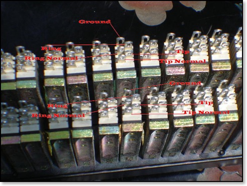
On Aug 1, 2011, at 11:24 PM, Benjamin wrote:
Thank you so much
Thanks again!
Benjamin -
 Toft ATB24 ConsoleNeed to wire a New Toft ATB24 Mixing ConsoleMichaelJuly 15, 2011 at 2:52 PM
I need to wire a studio and buy a patchbay. Here's the set up:
Lynx Aurora 16
Toft ATB24 console
Various preamps (more pre's than inputs!)
Toft has many I/O's
Recommendations for style of patchbay?
Thanks,
Michael
Hey Michael,
In general a solder-type patchbay cost less than other types. However, they take more time to setup. Also something to think about is when change is needed in your studio a few years from now, the solder type patchbays are not that fun to change.
Punch down style patchbays cost more but are quick to hook up and very easy to change down the road.
The patchbays with E3 connectors are easy to setup. The best thing about that type patchbay is the E3 connector can be quickly unplugged for a move or change.
A custom wired patchbay arrives ready to plug in but cost the most.
I will need a little more info from you. Can you supply more data?
-Bob
Michael:
I think I need to send a diagram of what we'd like so that we don't make a mistake in what we buy.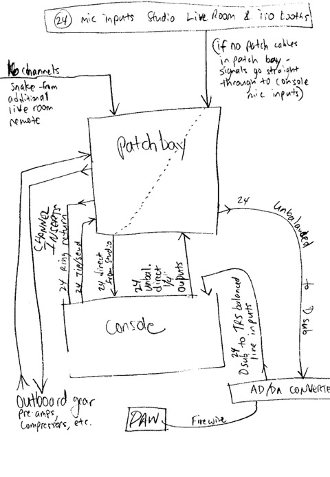
On Tue, July 15, 2011 at 2:53 PM, Bob Hickey
hey Michael,
After seeing you layout and thinking about your studio, I would suggest the Digital ADC 96 point patchbays:
The DAB3-14MKIVHN is a Half-Normal two rack unit, 3.5-inch, 96 Point TT Bantam Digital Audio Patchbay with QCP MKIV termination for easy punch down hook-up and normals-strapped audio normalling. ADC Pro Patch digital audio patchbays use the same durable enclosures and jacks as analog audio patchbays, but they are wired with precision 110 Ohm, low-capacitance, shielded twisted-pair cabling. This meets stringent AES digital audio standards and ensures against impedance mismatches that can cause bit errors. Solder-free internal wiring provides high reliability, much higher than soldered systems. High-quality longframe WECO jacks with self-cleaning wiping action - Superior reliability -Punchdown system with split cylinders for gastight connections - Quick and easy termination - Epoxy powder-coated steel chassis - Exceptional protection and durability - Precision 110 Ohm digital cable - Quality transmission for a lifetime of use. List $1,285.00 Mr. Patchbay Price $399.95
http://www.misterpatchbay.com/digital-patchbays/digital-patchbay.html
Here is my layout for your studio sir:
Top-Row of ADC 96 Point patchbay #1
Ch# Device Normal
1 Mic Input FN direct to console
2 Mic Input FN direct to console
3 Mic Input FN direct to console
4 Mic Input FN direct to console
5 Mic Input FN direct to console
6 Mic Input FN direct to console
7 Mic Input FN direct to console
8 Mic Input FN direct to console
9 Mic Input FN direct to console
10 Mic Input FN direct to console
11 Mic Input FN direct to console
12 Mic Input FN direct to console
13 Mic Input FN direct to console
14 Mic Input FN direct to console
15 Mic Input FN direct to console
16 Mic Input FN direct to console
17 Mic Input FN direct to console
18 Mic Input FN direct to console
19 Mic Input FN direct to console
20 Mic Input FN direct to console
21 Mic Input FN direct to console
22 Mic Input FN direct to console
23 Mic Input FN direct to console
24 Mic Input FN direct to console
Above are the Room #1 Microphone channels 1-24. These channels are Full-Normal going direct to console. No patch cable need.
25 Mic Room #2 NN
26 Mic Room #2 NN
27 Mic Room #2 NN
28 Mic Room #2 NN
29 Mic Room #2 NN
30 Mic Room #2 NN
31 Mic Room #2 NN
32 Mic Room #2 NN
33 Mic Room #2 NN
34 Mic Room #2 NN
35 Mic Room #2 NN
36 Mic Room #2 NN
37 Mic Room #2 NN
38 Mic Room #2 NN
39 Mic Room #2 NN
40 Mic Room #2 NN
Above are the Room #2 Microphone channels 25-40. These channels have No-Normals. A patch cable is needed for the above mics to reach the console.
41 MULT #1
42 MULT #1
43 MULT #1
44 MULT #1
45 MULT #2
46 MULT #2
47 MULT #2
48 MULT #2
Bottom-Row of ADC 96 Point patchbay #1
Ch# Device Normal
49 Console In #1 FN from mic input
50 Console In #2 FN from mic input
51 Console In #3 FN from mic input
52 Console In #4 FN from mic input
53 Console In #5 FN from mic input
54 Console In #6 FN from mic input
55 Console In #7 FN from mic input
56 Console In #8 FN from mic input
57 Console In #9 FN from mic input
58 Console In #10 FN from mic input
59 Console In #11 FN from mic input
60 Console In #12 FN from mic input
61 Console In #13 FN from mic input
62 Console In #14 FN from mic input
63 Console In #15 FN from mic input
64 Console In #16 FN from mic input
65 Console In #17 FN from mic input
66 Console In #18 FN from mic input
67 Console In #19 FN from mic input
68 Console In #20 FN from mic input
69 Console In #21 FN from mic input
70 Console In #22 FN from mic input
71 Console In #23 FN from mic input
72 Console In #24 FN from mic input
73 Console Direct Out 1 FN to AD/DA Converter
74 Console Direct Out 2 FN to AD/DA Converter
75 Console Direct Out 3 FN to AD/DA Converter
76 Console Direct Out 4 FN to AD/DA Converter
77 Console Direct Out 5 FN to AD/DA Converter
78 Console Direct Out 6 FN to AD/DA Converter
79 Console Direct Out 7 FN to AD/DA Converter
80 Console Direct Out 8 FN to AD/DA Converter
81 Console Direct Out 9 FN to AD/DA Converter
82 Console Direct Out 10 FN to AD/DA Converter
83 Console Direct Out 11 FN to AD/DA Converter
84 Console Direct Out 12 FN to AD/DA Converter
85 Console Direct Out 13 FN to AD/DA Converter
86 Console Direct Out 14 FN to AD/DA Converter
87 Console Direct Out 15 FN to AD/DA Converter
88 Console Direct Out 16 FN to AD/DA Converter
89 Console Direct Out 17 FN to AD/DA Converter
90 Console Direct Out 18 FN to AD/DA Converter
91 Console Direct Out 19 FN to AD/DA Converter
92 Console Direct Out 20 FN to AD/DA Converter
93 Console Direct Out 21 FN to AD/DA Converter
94 Console Direct Out 22 FN to AD/DA Converter
95 Console Direct Out 23 FN to AD/DA Converter
96 Console Direct Out 24 FN to AD/DA Converter
Top-Row of ADC 96 Point patchbay #2
Ch# Device Normal
1 Insert Send ch#1 FN
2 Insert Send ch#2 FN
3 Insert Send ch#3 FN
4 Insert Send ch#4 FN
5 Insert Send ch#5 FN
6 Insert Send ch#6 FN
7 Insert Send ch#7 FN
8 Insert Send ch#8 FN
9 Insert Send ch#9 FN
10 Insert Send ch#10 FN
11 Insert Send ch#11 FN
12 Insert Send ch#12 FN
13 Insert Send ch#13 FN
14 Insert Send ch#14 FN
15 Insert Send ch#15 FN
16 Insert Send ch#16 FN
17 Insert Send ch#17 FN
18 Insert Send ch#18 FN
19 Insert Send ch#19 FN
20 Insert Send ch#20 FN
21 Insert Send ch#21 FN
22 Insert Send ch#22 FN
23 Insert Send ch#23 FN
24 Insert Send ch#24 FN
25 Outboard Device 1 in
26 Outboard Device 2 in
27 Outboard Device 3 in
28 Outboard Device 4 in
29 Outboard Device 5 in
30 Outboard Device 6 in
31 Outboard Device 7 in
32 Outboard Device 8 in
33 Outboard Device 9 in
34 Outboard Device 10 in
35 Outboard Device 11 in
36 Outboard Device 12 in
37 Outboard Device 13 in
38 Outboard Device 14 in
39 Outboard Device 15 in
40 Outboard Device 16 in
41
42
43
44
45
46
47
48
Bottom-Row of ADC 96 Point patchbay #2
Ch# Device Normal
49 Insert Return ch #1 FN
50 Insert Return ch #2 FN
51 Insert Return ch #3 FN
52 Insert Return ch #4 FN
53 Insert Return ch #5 FN
54 Insert Return ch #6 FN
55 Insert Return ch #7 FN
56 Insert Return ch #8 FN
57 Insert Return ch #9 FN
58 Insert Return ch #10 FN
59 Insert Return ch #11 FN
60 Insert Return ch #12 FN
61 Insert Return ch #13 FN
62 Insert Return ch #14 FN
63 Insert Return ch #15 FN
64 Insert Return ch #16 FN
65 Insert Return ch #17 FN
66 Insert Return ch #18 FN
67 Insert Return ch #19 FN
68 Insert Return ch #20 FN
69 Insert Return ch #21 FN
70 Insert Return ch #22 FN
71 Insert Return ch #23 FN
72 Insert Return ch #24 FN
73 Outboard Device Output 1
74 Outboard Device Output 2
75 Outboard Device Output 3
76 Outboard Device Output 4
77 Outboard Device Output 5
78 Outboard Device Output 6
79 Outboard Device Output 7
80 Outboard Device Output 8
81 Outboard Device Output 9
82 Outboard Device Output 10
83 Outboard Device Output 11
84 Outboard Device Output 12
85 Outboard Device Output 13
86 Outboard Device Output 14
87 Outboard Device Output 15
88 Outboard Device Output 16
89
90
91
92
93
94
95
96
Great! we are prioritizing specifically what we will need... since we talked I purchased another 16 channels of AD/DA conversion and we will work that into the configuration. Our studio build out is progressing and we will be ordering the patchbays within a month.
Thanks!!!
Michael
-
 Overgrown home studioOvergrown home studio, looking for a TT patchbayJimOn July 4, 2011, at 8:07 PM
Hey there,
Hope all's well. Got a quick question for you. Got an overgrown home studio, and looking for a TT patchbay, probably w punch down assembly on the chassis. But I'd like something w the ability to be normaled, half, non, carry phantom, all that. Don't know much about these, but this seems to me the cheapest, easiest way to maintain the ease of assembly before switching over to a bay w 1/4" on both sides. Do you have any bays that fit that description in the 300 buck range? Thanks...much appreciated.
Ran
Hey Ran,
I will offer to sell you a used ADC Single-Space with remote punch panel that has the normals "brought out" to the remote punch panel ( you mount the remote punch panel on the rear rack rails...) letting you choose the normaling for each channel. That patchbay would include the free punch tool and this patchbay is easy to strap the ground for Phantom Power. Price $299.00 plus shipping. Let me know if you want one and I will make you a shopping cart. -Bob -
 New TT Patch CablesI need to buy some New Patch CablesJim ____On Jun 25, 2011, at 3:23 PM
Hello Bob
I am interested in ordering one of your used single-rack-space Switchcraft 96 point TT Bantam Patchbay.
I also need to buy some New Gold Two-Foot TT Bantam Patch Cables. These are Quad-Pair cables. However, I was not sure what you meant by "Quad-Pair" Are the four of the cables hooked together or something. I need at least the equivalent of 8 individual patch TT Bantam patch cables.
I would like to work something out right way, so you can ship by Monday for 3 day delivery.
Thanks, Jim
Hey Jim,
If you order the SwithCraft today, I can ship that unit on Monday.
Quad-pair sometime called star quad refers to the two leads inside the cable. This is done to balance the impedance and reduce noise. The hot connection(tip) and the balanced connection(ring) both have two cables twisted together like I show below. These cables sound great. All my clients who have bought these TT patch cables loves them and about half of those clients have returned for more patch cables. -Bob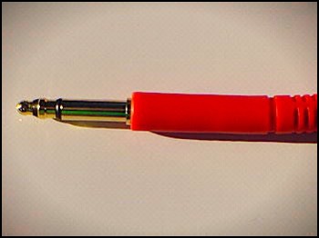
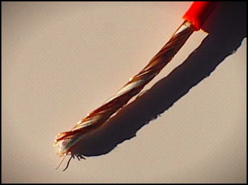
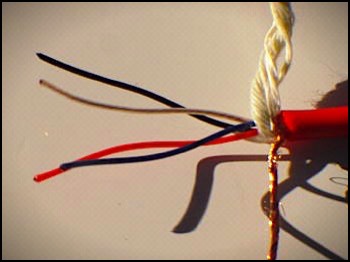
-
 Pro Tools PatchbayI was curious about the ADC pro tools patchbay...NilesOn Apr 22, 2011, at 4:02 AM
On Apr 22, 2011, at 4:02 AM, niles wrote:
hello,
i was curious about the ADC pro tools patchbay...
is it possible to get 24 channels from pro tools. and then the other side with nothing on it so i can wire up the XLR's myself? i'd be curious on a price for that if possible
thanks for your time!
-niles
On Apr 22, 2011, at 11:16 AM, Bob Hickey
Hey Niles,
That patchbay can be wired to match the recording studio’s needs. If I leave the bottom-row with bare-ends on the wires, I can discount the price by $80.00
On Apr 22, 2011, at 12:47 PM, niles wrote:
wonderful. thanks for answering everything.
I think I might do it... if it's something you'd do. first 24 on the db25s and the rest without anything so I can throw on XLR's
-niles
Bob
Yea, sure... it will be a good project for the weekend.