All About Patchbays
How can you solve the problem of quickly connecting all your recording gear in different configurations during a recording session? You use a patchbay.
What is a patchbay?
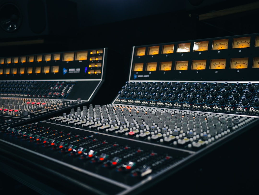
A patchbay is a passive device where audio signals route to and from all the recording gear in your studio. Our modern recording studio is a collection of various audio equipment all of which may have different input and output connectors on the rear of the units. The patchbay solves the problem of connecting all these different devices. The back side of your patchbay is where all your devices will connect to the patchbay. The front of the patchbay is where you route the input and outputs paths of your musical signals. You do this by "patching" a short patch cable point to another point on this patchbay or a spot on a different patchbay.
The significant advantage of adding an audio patchbay to any recording session is the fact that is speeds up of your workflow by allowing you to make connections between any audio equipment in the control room in seconds.
When do I need a patchbay?
You will know when it’s time to shop for a patchbay because you will begin to get annoyed that you are getting up from your control room chair again to go behind your equipment racks to unplug and plug cables. Many times we may find that the inner-connect cabling between the two devices will not be long enough or the wires have the wrong connectors to mate with the gear we want to use. If we spend too much time hooking up the cables between pieces of equipment, we may forget why we were even connecting the devices. A patchbay helps the audio engineer and or musician sustain a creative workflow.
If you charge money for your studio time or plan to in the future, no client will want to wait while you get to go to the back of your gear-racks to hookup a different mic preamp in the recording chain and then to another rack containing a compressor or a parametric equalizer. It is especially true if a musician is waiting in the vocal booth. In my personal experience, I have found that band members are not that good at waiting around for the engineer to make changes.
By the time you found the correct adapter and borrowed a cable from the other rack, the drummer has gone for a burger, the guitar player is on the phone with his girlfriend, and the bassist is well into a game of “Call of Duty” in the lobby. Not only that but, the guitar player’s location is unknown.
Mounting your patchbay close to your mixing chair will eliminate any unnecessary downtime. Moving the audio paths very quickly with your patch cords lets you return to the music in a snap to find just the right sound without ever leaving your chair!
How can I quickly understand patchbays?
Think of the patchbay as a matrix. Your patchbay becomes the train station in your studio where all your blazing audio signals arrive screaming down the tracks to the patchbay-station and leave to a different point in moments. You will be the conductor, and your patch cables will determine which path the audio signal you are working with will go.
Imagine that you turned all your recording equipment with the fronts facing the wall. What would you see? You now can see from the rear that some devices use different types of connectors which need to come together to make a musical recording. These audio devices will need to be plugged into each other in various configurations during every recording session.
How do I set up my patchbay?
I feel the best way to set up your patchbay is first to map out where you want all your studio recording equipment to appear on the face of your patchbay. Through the years of building custom patchbays, I have found that the standard setup seems to be all signal outputs are located on the top row while the inputs are below that on the bottom row.
One very convenient method for planning your layout is to download my "Blank Patchbay Spreadsheet" This Excel spreadsheet is ready to go with pre-set rows, device names, input channels, output channels, cable lengths, normalizing type and which connector for any given channel.
Standard Patchbay Design
I have also found that most studios start their patchbay design with the microphones and microphone tie lines on the left-hand side of the top row of the patchbay. Both our Mics and Mic tie-lines will have XLR-MALE connectors on the ends of the cables. Therefore these channels on the rear of the patchbay must use XLR-FEMALE connectors to accept the signal.
The channels below the microphone outputs are a great place for your Mic Pre inputs. The mic inputs of your mixing console can be in this spot on the bottom row too. In both cases, we use normals. More on normalization in the normals section below on this very page.
Next section of patchbay channels can be the actual recording in's and outs to your DAW. Using your Mic Pre outputs on the top row with the recording inputs to the DAW or any other recording device like a multi-track analog recorder on the bottom row is a logical signal path. These to-and-from recording channels should be either full-normal or half-normal. Half-normal gives you a choice to make two different sounds from one output.
After that section on the patchbay's top-row to the right of your Mic Pre outputs can be the DAW outputs. If you use a Summing Mixer, the bottom-row below the Pro Tools or other DAW outputs is a perfect place for summing inputs.
The next section to the right will be a good place for your effects in's & outs. Always remember this rule: Effects use no normals. Both full and half normal will send the outputs returning to the inputs and create a feedback loop.
The remaining patchbay channels on the far right side are for master stereo paths or 5.1 surround paths, headphone cue mixes, aux sends and returns plus talkback lines.
View examples of patchbay layouts from other recording studios here.
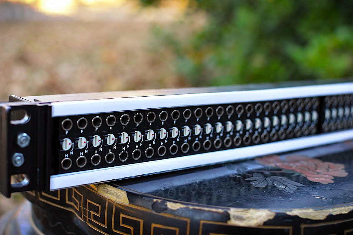
How to understand Normals
No Normal
Is when the top row is independent of the bottom row.
Straight Thru
The same as no normal. None of the jacks are connected. You must use a patch cable to make a connection.
Full Normal / Normal Strapped
Inserting a patch cable into either row breaks the signal path. The signal follows the patch cable. Each jack on the top-row is connected to the jack under it on the bottom row. Allowing the audio or video signal to "pass-through" the patchbay without using a patch cable. When we want to change the "normal" signal path we can use a patch cable to change the destination of the signal.
Half-Normal
Place a patch cable into the bottom-row breaks the signal path. Placing a patch cable into the top-row allows the signal to still go to the jack under it on the bottom-row (without breaking the normal) and also follows the patch cable.
Each jack on the top-row is connected to the jack under it on the bottom row. Allowing the audio or video signal to "pass-through" the patchbay without using a patch cable. When we want to change the "normal" signal path we can use a patch cable to change the destination of the signal.
Custom Patchbays
Custom patchbays are made to be plug & play. Leaving all the cable stripping and soldering to the pros. Whatever your needs are, Mr. Patchbay completes your order quickly at reasonable prices.
TT Patchbays
TT Patchbays use tiny telephone jacks which refers to the size of the points in the patchbay. Sometimes called Bantam, this size audio jack gives you twice as many patch points for the same space as standard quarter-inch jack.
1/4" TRS
1/4" TRS Patchbays Quarter inch refers to the diameter of the jacks used in these patchbays. TRS is a balanced audio path using the Tip, Ring, and Sleeve to transfer audio.
To my knowledge all patchbays that use female quarter inch on the front as well as the back of the patchbay use guitar type jacks. More times than not these lose a DB or two, sound dull on the top end and soon begin to make that "crackly" sound. Mr. Patchbay builds a Pro Audio ¼" bay that has both front & rear jacks. You can view this Pro Audio 1/4" TRS 48 Point Custom patchbay here.
DB-25 / D-Sub
DB-25 is a type of connector that is very common in Pro Audio gear today. This type connector is also called D-Sub. The DB-25 snake carries eight channels.
Punch Down
Patchbays that are Punch-Down type means NO SOLDERING is needed. A punch tool not only strips the wire for you, but it also cuts the excess cord off as well. It's a snap! Punch-Down patchbays takes much less time than soldering patchbays.
ELCO / E3
ELCO and EDAC are the same connectors made by different companies. ELCO is a brand name of connectors which were very popular in the 1980s and 1990s. To my knowledge, all of the first digital 8-track recorders called an ADAT used the 56 – Pin ELCO connectors. The three pin ELCO connector call the E3 is still popular in pro audio recording today
ElLCO connectors come in many sizes. The term E3 refers to a 3-pin ELCO connector. The E3 is quick and easy to connect and disconnect.
XLR Panels
XLR Patchbays are for microphones which have 3-pin connectors used in balanced microphone lines and line-level signals. Recording studios use XLR panels between the live room and the control room.
Patchbay History
In the mid-seventies, the heart of my first recording studio centered around an analog eight-track reel-to-reel recorder. While local musicians waited, I scrambled around behind the recording gear trying to make audio connections. I was trying to unplug my equalizer and plug in one compressor my LA-3A to a different channel on the mixing board again. That is when I found my desire for a patch bay.
After a little shopping trip to my local music store, I looked at the new patchbay sitting in my lap thinking: "How do I even wire this up?" After staring at the bay for a few minutes, I understood that all my recording gear needed to plug into the back of the patchbay. I would then use the front side of the patchbay to connect and disconnect different audio devices in my home studio while recording songs.
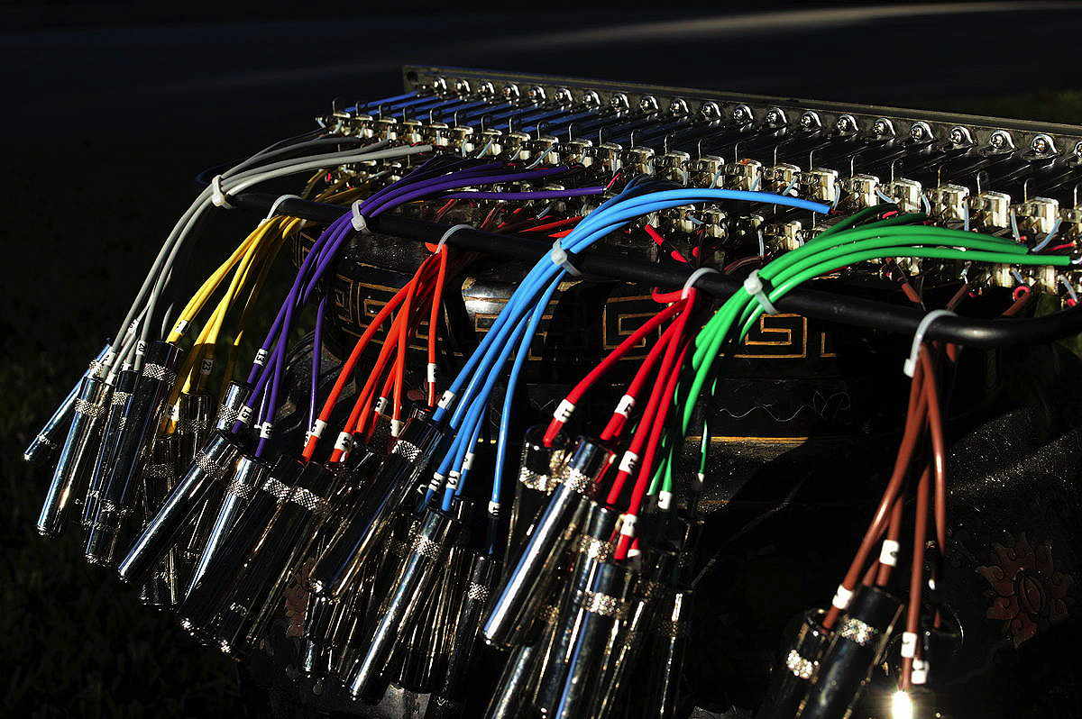
The first lesson I learned: Labeling the front of the patchbay is mandatory. You need to know where all those cables you plugged in the back show up on the front of the patch bay.
I found out that the holes in a patchbay are points. So with no guidance, I began to plug my recording gear into the points on the back side of the patchbay. My four outputs from my mixer plugged into the top four positions. On the row of points below that, I connected the eight inputs to my recorder. I then sent the output from my compressor into another location on the top row. Likewise, I plugged into the LA-3A compressor to the channel below the output point. That was easy, and the benefits of using a patchbay were about to pay off.
Soon after that, I found myself with a guitar player wanting to over-dub his solo plus a vocalist ready to lay down tracks. Now with my patchbay, I could make changes to different channels quickly and move the compressor between the output of the mixer and the next instrument to be recorded. Adding an audio patchbay to my studio was one of the best investments I ever made.